I purchased a kit from a member, but the SMD resistor values doesn't match the shcematic from the first page. Any reason for that?
You need to read the first post right to the bottom...
There's a link posted there to the updated schematic and assembly instructions:
http://www.diyaudio.com/forums/soli...-lme49830-lateral-mosfets-75.html#post2920157
The attachments in the first post cannot be modified, which is why there is a big warning in bold letter with the updated post and attachments.
Cheers,
Owen
I purchased a kit from a member, but the SMD resistor values doesn't match the shcematic from the first page. Any reason for that?
Look at Post #742.
")
Enjoy,
Neel
Fault finding...
Wow, this thread was way back down the list. Took ages to find...
For starters, not a huge up-date from me just more fault finding. Both dps-600's have been up & running after hurting them and one of the amps.
One amp appears to be running fine, however, it's reading 70 to 80 mV on the output with the dps-600. Need to check this with a lower V supply.
The broken & fixed [supposedly] amp was showing some high readings at the output and this [hopefully] has been traced to the P-channel FET. Please, is THIS the correct part?
The DPS-600's now won't start-up with a load =>50mA... Grounding issue perhaps???
|-O-|
Purchased a Raspberry Pi [arrived yesterday] and that got me iching over getting the amps up and running once more. Thoughts are to ditch the dps-600's and go for a lower +/- 20 to 25V supplies...
Regards
Paul
Last edited:
Hi Paul,
Send me a PM with your address and I can see if I can mail you a replacement fet. I have a few extras and it will save you buying it.
You problem does indeed sound like grounding issue, as that's the only thing I can think of that would cause a DC offset that high. The only other thing might be grossly mismatched rails on the LME, but even that shouldn't be an issue.
What version are you building? Did you follow the guide closely?
A few pictures might help as well.
Cheers,
Owen
Thanks Owen, PM sent...
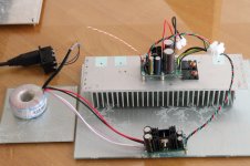
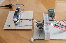
Amp setup, SE AC coupled build spec as per build guide.
Amp A - Setup A: Bias; minimum, single The Wire psu +/- 23 VDC rails. Measured 1.4mV offset at speaker output. Measured 2.5 to 3 Vdc spike on powering off at speaker output.
Amp A - Setup B: Bias; minimum & 360 mA, dps-600 +/- 55/45 VDC rails. Measured -0.8mV offset at speaker output. Measured 2.5 to 3 Vdc spike on powering off at speaker output.
Amp B - Faulty / blown P-channel fet. Replaced LME, mute components and a few smd caps.
DPS-600 - Initial power up using soft start switch, OK at 360 mA bias.
DPS-600 powering down to power up behaviour [on off on]: bias => 50mA
< 5 sec gap, power up failure.
=> 5 sec gap, power up successful.
Grounding - Uncased, both the remote soft-start switch [dps-600] and small wire on the signal input, cause slight variations on the measured offset as they are moved / touched.
Paul
Attachments
Last edited:
DPS-600 powering down to power up behaviour [on off on]: bias => 50mA
< 5 sec gap, power up failure.
=> 5 sec gap, power up successful.
This sounds like DPS600 protection taking time to reset ...
I am in the process of matching fets for the next wire project. +/- 80/90 volt rails, 3 parallel pairs per channel. The fets I received were in 2 seperate plastic tubes, 10 in each tube. The 5th fet in one of the tubes that I thought were all N channel fets was a P channel. I didn't find this out till after hooking the fet up to the test jig that I made. No smoke and it appears to work ok when hooked up properly. All the fets so far are close to each other in parameters. I am matching at 150ma and 1 amp current. They are much closer than bjt's.
The first wire amp has been running pretty much every day. It's still running and sounding fantastic. Many thanks again Owen.
The first wire amp has been running pretty much every day. It's still running and sounding fantastic. Many thanks again Owen.
I am in the process of matching fets for the next wire project. +/- 80/90 volt rails, 3 parallel pairs per channel. The fets I received were in 2 seperate plastic tubes, 10 in each tube. The 5th fet in one of the tubes that I thought were all N channel fets was a P channel. I didn't find this out till after hooking the fet up to the test jig that I made. No smoke and it appears to work ok when hooked up properly. All the fets so far are close to each other in parameters. I am matching at 150ma and 1 amp current. They are much closer than bjt's.
The first wire amp has been running pretty much every day. It's still running and sounding fantastic. Many thanks again Owen.
multisync i would like to buy 2 pairs of the spares if you want.i plan on two parallel pairs per channel and +/-70/80 volts rails. it would be nice if you share the test jig too.
I bought some two weeks ago at Newark/element14.
I would also like to see a sch. of the matching jig as well
Are you just going to add pairs to the existing ckt?
Any ballasting R?
How about S/S protection, any?
Stock No:
23T0783 Manufacturer Part No: ALF16N16W UOM Each/1 Quantity: 8 Price: $7.70 Extended Price: $61.60
Stock No:
23T0787 Manufacturer Part No: ALF16P16W UOM Each/1 Quantity: 8 Price: $12.06 Extended Price: $96.48
Last edited:
I am using 2 power supplies, 24 volt 6 amp and 15 volt 1 amp.
I am using 2 Fluke 87's for measuring. 4 1/2 digit
I measure the voltage across the 10 ohm resistor at 2 current levels, 150ma and 1.00 amp, 1.500volts and 10.00 volts across the 10 ohm resistor give the current readings. When testing the 1 amp current I let the fet warm up for a minute, the current decreases as the fet warms up, then is steady. I use a large heat sink to screw down the transistor with an insulator.
I use a 10 turn pot to adjust the Vgs as a single turn is too sensitive to changes of VGs. esp when using 4 digits. I re adjust as the fet warms up to get the desired readings
I adjust the gate voltage to give the specific Ids current ie 150ma and 1 amp.
Masking tape on the fets is labeled 1-8 for the N channel and 11 to 18 for the P channel.
I keep notes on a sheet of paper. No graphs or plots.
For the LME board I will change out the 5.49kohm resistors for 10kohm 1/2 watt that I bought. With +/- 80 volt rails the 10k's will disapate about 0.3 watts at full output. Absolute worst case is about 0.6 watts with near DC freaquencies. I will keep the 220ohm gain resistors, gain will be about 45. Target is 50 volts RMS @ 8 ohms.
150ma is the bias current I used in the first build and I will probably use this value again.
1 amp through 3 pairs will be about 70 watts into 8 ohms, more than enough for 99.9% of my intended listening.
The application note from semlabs and several books I read indicate that I do not need source resistors for Lateral fets. I will try the amp without sourse resistors first and see what happens. I bought some 3 watt 0.1ohm 1% just in case. I bought some 220ohm 1/4 watt resistors and 330ohm 1/4 watt resistors for the gates.
I won't have any spares to give away. I will have 2 pair left for spares.
I see they are available at a few places now, not like last year.
Attachments
I'm done matching the fets and it turns out I didn't have to. I made another little circuit with 2 fets in parallel driving a common load and measured the current through both fets. I choose 2 fets with the largest difference in readings.
testing fets one at a time
fet #11 Vgs 1.740V for a current of 1.000 amps through 10 ohm load.
fet #18 Vgs 1.712V for a current of 1.000 amps etc....
fets in parallel.
Ids fet #11 0.473 ma
Ids fet #12 0.500 ma
difference is less than 6%
from the schematic I measured the voltage across the 2ohm resistors to get the current.
hopes this helps someone
Attachments
nobody else is afaik, its pretty niche and semelab is a MAJOR manufacturer, one of the, or possibly the largest manufacturer of linear discrete parts these days. they are manufactured under the name Class D, Alfet, Exicon etc, but the ALFET are the only dual die plastic package I think. why? are you having trouble sourcing them?
nobody else is afaik, its pretty niche and semelab is a MAJOR manufacturer, one of the, or possibly the largest manufacturer of linear discrete parts these days. they are manufactured under the name Class D, Alfet, Exicon etc, but the ALFET are the only dual die plastic package I think. why? are you having trouble sourcing them?
no i have two pairs and i wonder if the rest i will buy will be the same.
- Home
- Amplifiers
- Solid State
- "The Wire AMP" Class A/AB Power Amplifier based on the LME49830 with Lateral Mosfets