I re read the application notes and I am comfortable with the fact that the amplifier will not runaway regardless of how hot it runs. For those of us who wish to parallel some fets the application note also covers this. Another item that is interesting is the application note describes 2 current limiting suggestions without the use of source resistors.
Attachments
Last edited:
Hi Guys,
Wow! Lots of action on here all of a sudden! It's good to see people are working hard on this")
Let's see if we can address these issues one at a time:
Bias Stability:
I tested this pretty extensively as it was something I was concerned about since there is no thermal compensation for the bias.
The drifting you're seeing is relatively normal for any un-compensated amplifier, and mimics the behavior of most class A amplifiers. The temperature co-efficient of the lateral mosfets varies with the Id and realistically, you'll need at least 300mA for things to stabilize relatively quickly. The important part is that if you set the amps at 300-400mA when they are at full operating temp, then you can be assured that they will return to exactly that value the next time you start them up and they get back up to temp. The bias might be a bit on the low side when starting from cold, but should be in the ballpark after about 10 minutes.
The above posted app note talks a lot about bias stability, but keep in mind that all the numbers and charts they use are for the 8A parts, and everyone here is using the 16A parts which require twice the bias current as they are simply two closely matched 8A dies on the same substrate. That means to get the performance they're talking about in the article, you need at least 250mA of bias.
Multisync: If you have a heatsink that is a little bit bigger, try the same test with about 360mA of bias on the fets. I think you'll find that they settle in much more quickly, and are more tolerant of HS temp changes. If you don't have one, I could always lend you one from my pile
Feedback Resistor Power Rating
If you are indeed going to be running the amplifier at high power for extended periods of time, or running higher voltage into a high impedance load, then you might indeed consider increasing the power rating of this resistor. As it is, I would feel pretty comfortable running that little resistor at 1/4 watt full time, and 1/2 watt transients should not be an issue. If you are running very high power for prolonged periods of time, then I would suggest stacking two 0805 resistors vertically on those pads and using twice the resistance. this improves the heat dissipation area by a factor of two, and should give even more margin.
LME Temp
This again is an question of "how hot is too hot". The LME49830 will happily run all day long at 80C, and doesn't start scaling back performance in protection mode until 150C. I too have a tendency towards feeling sympathy for silicon when it comes to temperature, and being conservative is always a good thing, but if that HS is sitting at 60C then you really have nothing to worry about, and the long term reliability will not be impacted.
Give page 12 of the datasheet a quick read over for more details on this. To quote National directly from the LME datasheet:
"The choice of a heat sink for any power IC is made entirely to keep the die temperature at a level such that the thermal protection circuitry is not activated under normal circumstances."
Also keep in mind that the power draw for the LME is constant regardless of output power level. That means you don't need to build in margin above and beyond the normal operating temp of the device.
The only real concern I have is for the electrolytic caps in the vicinity of the heatsink, as their lifetime and performance will be degraded if they are constantly sitting at 80 or 90C. As for the IC, I really have no concerns.
Cheers,
Owen
Wow! Lots of action on here all of a sudden! It's good to see people are working hard on this
Let's see if we can address these issues one at a time:
Bias Stability:
I tested this pretty extensively as it was something I was concerned about since there is no thermal compensation for the bias.
The drifting you're seeing is relatively normal for any un-compensated amplifier, and mimics the behavior of most class A amplifiers. The temperature co-efficient of the lateral mosfets varies with the Id and realistically, you'll need at least 300mA for things to stabilize relatively quickly. The important part is that if you set the amps at 300-400mA when they are at full operating temp, then you can be assured that they will return to exactly that value the next time you start them up and they get back up to temp. The bias might be a bit on the low side when starting from cold, but should be in the ballpark after about 10 minutes.
The above posted app note talks a lot about bias stability, but keep in mind that all the numbers and charts they use are for the 8A parts, and everyone here is using the 16A parts which require twice the bias current as they are simply two closely matched 8A dies on the same substrate. That means to get the performance they're talking about in the article, you need at least 250mA of bias.
Multisync: If you have a heatsink that is a little bit bigger, try the same test with about 360mA of bias on the fets. I think you'll find that they settle in much more quickly, and are more tolerant of HS temp changes. If you don't have one, I could always lend you one from my pile
Feedback Resistor Power Rating
If you are indeed going to be running the amplifier at high power for extended periods of time, or running higher voltage into a high impedance load, then you might indeed consider increasing the power rating of this resistor. As it is, I would feel pretty comfortable running that little resistor at 1/4 watt full time, and 1/2 watt transients should not be an issue. If you are running very high power for prolonged periods of time, then I would suggest stacking two 0805 resistors vertically on those pads and using twice the resistance. this improves the heat dissipation area by a factor of two, and should give even more margin.
LME Temp
This again is an question of "how hot is too hot". The LME49830 will happily run all day long at 80C, and doesn't start scaling back performance in protection mode until 150C. I too have a tendency towards feeling sympathy for silicon when it comes to temperature, and being conservative is always a good thing, but if that HS is sitting at 60C then you really have nothing to worry about, and the long term reliability will not be impacted.
Give page 12 of the datasheet a quick read over for more details on this. To quote National directly from the LME datasheet:
"The choice of a heat sink for any power IC is made entirely to keep the die temperature at a level such that the thermal protection circuitry is not activated under normal circumstances."
Also keep in mind that the power draw for the LME is constant regardless of output power level. That means you don't need to build in margin above and beyond the normal operating temp of the device.
The only real concern I have is for the electrolytic caps in the vicinity of the heatsink, as their lifetime and performance will be degraded if they are constantly sitting at 80 or 90C. As for the IC, I really have no concerns.
Cheers,
Owen
Excellent! Glad to hear you got it sorted.
The added noise from those resistors should not be an issue given the existing noise floor from most PSU's. If you were running fully regulated linear supplies on both the output devices and the LME, then you might be able to measure the difference, but you certainly wouldn't be able to hear it. With any normal PSU the noise contribution of those resistor value increases will be completely swamped.
Cheers,
Owen
can you measure noise that low? =) would have thought this amp would be below the noise floor of most peoples kit, so an increase in noise may not be picked up.I can not see or measure any increase in noise.
here is the quote, but then if you are happy with noise lower than your measuring gear, then I suppose...meh..

Ahh... yes. I was referring specifically to the balanced configuration for that comment.
The SE configuration starts with much lower resistors values, so what multisync has done is effectively increase the resistor value to match what is used on the BAL arrangement. There will be roughly a 1-2dB noise floor penalty, but nothing to get worked up about.
Notice his Rf value is 30k, just like in the balanced version, and his Ri is a little lower at 900 ohms because the gain is a little higher, which will also impact the noise floor by a few dB.
All in all, it's just a matter of personal preference and needs, and in this case it sounds like the small increase in noise floor is justified by the peace of mind with that feedback resistor and the need for a little more gain.
Cheers,
Owen
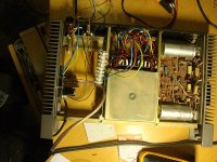
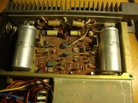
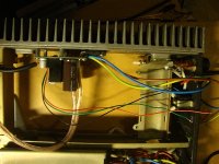
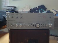
Well, at last found out how to add pictures to message
Both amps are running and behaving well, DC offset on both outputs is about 1mV.
Did some mistakes while assembling, luckily didn't blow up anything. One mistake to mention, i used screws with too large head for mounting, screwhead touched ac coupling cap. That made DC offset on one amp to rise to 70mV, second amp started to oscillate.
At the moment lme's and fets are running on +-32V unregulated, will try to fit into frame separate regulated +-40V psu for lme's.
Maybe a dumb question, would it be a good idea to add some additional capacity to fet rails? Now there are only 1000microF caps on pcb.
Attachments
DIGORA
Yes, pairs of 2SK1058/2SJ162s can be used in place of the dual die Alfet lateral MOSFET devices without additional drivers after the LME49830. However, they should have separate gate resistors, and I strongly recommend adding individual source resistors to facilitate current sharing between the parallel devices. Try the same gate resistors as are in OPC's design. As for the source resistors, I recommend 0.22 or 0.33 ohm, 3 watt film (example: Panasonic ERX-3FJSR33Ehttp://www.mouser.com/ProductDetail...=sGAEpiMZZMtlubZbdhIBIJEI43P/haKmrTbHoL2Wqr4=). Note: the Alfet application note explains that the dual die devices do not require the source resistors because their manufacturing process produces extreemly well-matched pairs in each dual die device. (Search: "applicationnotealfet" for a pdf copy of the application note.) Multiple 2SK/2SJ devices should provide comparable results to the Alfets.
However, you will need to keep the leads as short as possible. This is especially important for the gate resistors.
Happy New Year
The current output from the LME should be ample to charge the mosfets capacitance for at least 8 devices. My calculation seemed to show that more than that would be fine, I forget just now. I'm maybe using 10 mosfets, just for a laugh probably won't hear the difference from 8 (4 pairs), or maybe less than that, but worth a try just in case. Though I converted a Hafler DH200 from 4 to 6 and didn't hear the difference with my speakers.
I'm going to use four pairs of these mosfets per mono block and don't intend to source resistors. In my experience with bipolar transistors they change the sound. Each different type sounded different. Used Caddocks in the end but because we all heard the improvement. So if they change the sound, best to not use them at all unless it's necessary.
The gate resistors should be close to each mosfet, ie, soldered onto them.
You might want to add a 22pF polystyrene across each mosfet gate and drain.
probably won't hear the difference from 8 (4 pairs), or maybe less than that, but worth a try just in case. Though I converted a Hafler DH200 from 4 to 6 and didn't hear the difference with my speakers.Would that 0.22 or 0.33 not be swamped by the 6Ω(?) resistance of each mosfet? I looked at the data sheet but there's nothing there about resistance.As for the source resistors
I'm going to use four pairs of these mosfets per mono block and don't intend to source resistors. In my experience with bipolar transistors they change the sound. Each different type sounded different. Used Caddocks in the end but because we all heard the improvement. So if they change the sound, best to not use them at all unless it's necessary.
The gate resistors should be close to each mosfet, ie, soldered onto them.
You might want to add a 22pF polystyrene across each mosfet gate and drain.
Last edited:
That sucks BMS, I know the feeling though!
I've got a case and heatsinks on the way at last. I hoped that they would arrive this week just gone (though that was a touch optimistic given they shipped only on Christmas eve). With that (and FETs arriving at qusp's in the NTD1 parcel from Owen soon too) I'll have everything I need to start building up my 2xLPUHP and 2xLME49830 The Wire amps in the one enclosure. I've been building some mounting/heatspreader plates for LPUHP amps and DPS600. The challenge comes in that this build is really a drawn out process, because I want to add my extra automation board to the mix too. \
Build timeline for me looks something like:
1. build it all and mount one amp on a heatsink, then measure real world bias pot resistance for my fets+heatsink.
2. complete my bias/mute/thermal protection board design/layout
3. then with the extra board design completed I'll do a final build and all the front/rear panel trimmings.
Realistically, knowing how my projects pan out, I think I'll be lucky to have my build in a final case before Easter, though I hope to have given it a test run before then.
- Home
- Amplifiers
- Solid State
- "The Wire AMP" Class A/AB Power Amplifier based on the LME49830 with Lateral Mosfets