It has been suggested that the Vgs should be limited to 10V and then use some sort of thermal sensor to turn off the amplifier when the HS reaches 70-80 Degrees Celsius.
That could be implemeted with some sort of transistor arrangement that turns off the drivers when reaching 70-80 Degrees Celsisus. Maybe shunting the voltage from the VAS to the 2 BJT drivers to ground would do the trick? Just 2 transistors, one on each base input of the drivers, then connected to the thermal sensor.
Btw, using an output stage with BJT drivers for the Lateral FETs.
EDIT : Something like attached schematic.
Attachments
Last edited:
Depending on the use (ie as personal use, commercial or for retail sale etc,), there may be no need at all for output limiting with lateral Mosfet output stages.
I have built, used and then sold around 20 Mosfet amps in the power range of 50-200W over the many years since Hitachi introduced the parts. None have had limiters and none, to my knowledge, ever failed due to overcurrent - such is the reliability of the thermal self-limiting in conservative AB amplifier designs.
For personal use, I can't see any reason to fit limiters but there will always be crazy loads and fault conditions which suggest something more positive and fast acting in commercial high power applications. I guess we're not considering that use and can rely on the main drawcards of laterals, which is inherent short circuit immunity, load sharing and extreme ruggedness.
Depending on the use (ie as personal use, commercial or for retail sale etc,), there may be no need at all for output limiting with lateral Mosfet output stages.
I have built, used and then sold around 20 Mosfet amps in the power range of 50-200W over the many years since Hitachi introduced the parts. None have had limiters and none, to my knowledge, ever failed due to overcurrent - such is the reliability of the thermal self-limiting in conservative AB amplifier designs.
For personal use, I can't see any reason to fit limiters but there will always be crazy loads and fault conditions which suggest something more positive and fast acting in commercial high power applications. I guess we're not considering that use and can rely on the main drawcards of laterals, which is inherent short circuit immunity, load sharing and extreme ruggedness.
Private use only, 3 Pairs of 16A, 250W, TO-264 Lateral FETs in the output.
Approximately 125-135 Watts into 8 Ohm with 48 Volt supply rails for the driver+output stage.
Going to drive floorstanders with 8 ohm nominal impedance, dropping to about 4 Ohm somewhere in the low bass area.
Another thing, now that you mentioned that you have built over 20 Lateral FET amps through the years, I have a question for you. Do you use source resistors when paralleling several pairs of Lateral FETs or do you just match them?
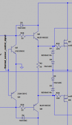
It has been suggested that the Vgs should be limited to 10V and then use some sort of thermal sensor to turn off the amplifier when the HS reaches 70-80 Degrees Celsius.
That could be implemeted with some sort of transistor arrangement that turns off the drivers when reaching 70-80 Degrees Celsisus. Maybe shunting the voltage from the VAS to the 2 BJT drivers to ground would do the trick? Just 2 transistors, one on each base input of the drivers, then connected to the thermal sensor.
Btw, using an output stage with BJT drivers for the Lateral FETs.
EDIT : Something like attached schematic.
Well, my brain wasnt working properly when I thought of that.

I could just use the thermal sensor circuit to mute the amplifier input instead. So much easier. Just 1 transistor on the input, shunting it to ground would do the trick.
As already said , the protection circuit must be connected to the drivers
bases not directly to the fet s gates....
Relevant circuitry must then be implemented to limit the vas current.
As connected in your schematic , the drivers would not survive if ever the
protection start to conduct.
bases not directly to the fet s gates....
Relevant circuitry must then be implemented to limit the vas current.
As connected in your schematic , the drivers would not survive if ever the
protection start to conduct.
As already said , the protection circuit must be connected to the drivers
bases not directly to the fet s gates....
Relevant circuitry must then be implemented to limit the vas current.
As connected in your schematic , the drivers would not survive if ever the
protection start to conduct.
Then my question is, why?
EDIT : Ah, think I understand now. If the protection starts to conduct in some sort of fault condition, the current the drivers will try to deliver could reach alot higher levels than what the drivers are biased at. Right? Basically I could fry my drivers. However, wouldnt the most likely scenario be the zeners going up in smoke first?
The protection is there to protect from gate-source voltages reaching more than 20 V. Here the voltage is restricted to about 10V.
VAS current is limited to about 10 mA, both LTP and VAS uses a CCS.
Last edited:
When overbiaised , diodes goes short circuits...Then my question is, why?
However, wouldnt the most likely scenario be the zeners going up in smoke first?
A good question, because these designs were similar, using Video Driver BJTs in a VAS with Current Source and various buffer stages plus 1-3 Mosfet output pairs. They date from the 1980s-90s and used simple 0R22 source resistors without matching, as the necessity with BJTs is much reduced here by current sharing. However, some folks will want to match anything that produces audio, in an effort to minimise distortion. I've compared a similar design with the same but matched TO3 devices and not heard a worthwhile difference when driven hard into inefficient 4-way speakers - perhaps occasionally clipping.Another thing, now that you mentioned that you have built over 20 Lateral FET amps through the years, I have a question for you. Do you use source resistors when paralleling several pairs of Lateral FETs or do you just match them?
Bob Cordell has some interesting comments in his book regarding Mosfet matching because of particular concerns with Hi-fi at lower levels. Given the enormous potential cost of matching these expensive parts, it's some relief that he trusts "same tube" batch consistency, since just the threshold voltage can then be used to determine transconductance.
Unfortunately, I can't comment on amplifiers without source resistors. I am only sure of having listened to a few inexpensive automotive types.
Last edited:
A good question, because these designs were similar, using Video Driver BJTs in a VAS with Current Source and various buffer stages plus 1-3 Mosfet output pairs. They date from the 1980s-90s and used simple 0R22 source resistors without matching, as the necessity with BJTs is much reduced here by current sharing. However, some folks will want to match anything that produces audio, in an effort to minimise distortion. I've compared a similar design with the same but matched TO3 devices and not heard a worthwhile difference when driven hard into inefficient 4-way speakers - perhaps occasionally clipping.
Bob Cordell has some interesting comments in his book regarding Mosfet matching because of particular concerns with Hi-fi at lower levels. Given the enormous potential cost of matching these expensive parts, it's some relief that he trusts "same tube" batch consistency, since just the threshold voltage can then be used to determine transconductance.
Unfortunately, I can't comment on amplifiers without source resistors. I am only sure of having listened to a few inexpensive automotive types.
Hmm, so one could do without maching with 0R22 source resistors?
Also, I have Cordells book and I did read that part, but although FETs from same batch should usually be fairly close one cant be certain without matching.
Matching expensive Lateral FETs could get really, really expensive. At something like 7.8£ for the Exicon 16A, 250 W devices from Profuisonplc matching 2 sets of 3 pairs of N channel and 2 sets of 3 pairs of P channel FETs would not be cheap.
Have to think about this, either no matching, but 0R22 source resistors or matching and then a smallar source resistor of 0R1.
I don't think the source resistors reduce the need for matching. They don't have the same degree of effect as with BJTs because of the Mosfet's inherent low transconductance or resistance. I believe that is the justification for eliminating them in some designs. The situation for BJTs is clear though; matching reduces distortion significantly in high power amplifiers in the area from 0.02% THD down to maybe 0.001%.Hmm, so one could do without maching with 0R22 source resistors?
This would seem more obvious with big arrays in pro. gear as I find much less improvement with just 2 pairs in a domestic design and this is not claimed to be a matching issue (ref. Self - The load invariant amplifier)
It would need evidence to be certain but we can assume there is some percentage of that improvement available for matched Lateral Mosfets. Let's say we can halve the THD or better at around 10 WRMS. That may be significant to some folks. It would be interesting to hear from others who have tested THD with small numbers of matched mosfet pairs. You can be sure anyone going to the trouble of matching would want to confirm the result too.
Regarding sources: Semelab produce the wafers, market their own Lateral Mosfets and supply Profusion, Magnatech plus others with chips for packaging. You can get better prices on essentially the same devices in Europe this way, I understand.
Regarding sources: Semelab produce the wafers, market their own Lateral Mosfets and supply Profusion, Magnatech plus others with chips for packaging. You can get better prices on essentially the same devices in Europe this way, I understand.
Can get the Semelab/Magnatec devices through Farnell. The Semelab Alfet series in TO-264 are equivalent to the TO-264 Laterals from Exicon(Profusionplc). The same goes for many other Semelab Laterals.
Buying from Profusionplc is about 20% cheaper than getting the Semelab Alfets through Farnell. You can get the Semelab BUZ family in TO-3 from Exicon as well, same die and package but the price is about half of what Farnell charges.
I have been in contact with both Semelab and Profusionplc, Profuisonplc aknowledged that their TO-264 Laterals are the same as the ones from Semelab/Magnatec.
Basically, it is the same single/dual dies in various different packages, supplied to several different vendors with Profusionplc being the absolute cheapest source.
Last edited:
I don't think the source resistors reduce the need for matching. They don't have the same degree of effect as with BJTs because of the Mosfet's inherent low transconductance or resistance. I believe that is the justification for eliminating them in some designs. The situation for BJTs is clear though; matching reduces distortion significantly in high power amplifiers in the area from 0.02% THD down to maybe 0.001%.
This would seem more obvious with big arrays in pro. gear as I find much less improvement with just 2 pairs in a domestic design and this is not claimed to be a matching issue (ref. Self - The load invariant amplifier)
It would need evidence to be certain but we can assume there is some percentage of that improvement available for matched Lateral Mosfets. Let's say we can halve the THD or better at around 10 WRMS. That may be significant to some folks. It would be interesting to hear from others who have tested THD with small numbers of matched mosfet pairs. You can be sure anyone going to the trouble of matching would want to confirm the result too.
There seems to be no accurate answer when it comes to using source resistors in FET amps or matching of FETs, in particular Lateral FETs.
You are right in that source resistors really dont do much for current sharing, Cordell said so as well in his book. Source resistors are more or less worthless when it comes to forcing current sharing between parallel output FET pairs. However, they can in SOME cases reduce THD by a small amount, but whether or not it is worth it I really dont know.
The matching issue is something else entirely. Due to the negative tempco of Lateral FETs at a drain current of about 100-300 mA, matching should really not be needed. They should more or less be sharing the current between them roughly equally. However, once again opinions seem to differ a lot on this.
Last edited:
Farnell prices? - same deal here!
Farnell - hate their prices, but they have most of what I need and they ship day to day.
But still wish they werent so damn expensive.
- Status
- This old topic is closed. If you want to reopen this topic, contact a moderator using the "Report Post" button.
- Home
- Amplifiers
- Solid State
- Lateral FET current limiting