A couple weeks ago, I purchased a Crown Com-tech 400 and with DJK's help I was able to resurrect channel 1 (which had a shorted Triac).
Not wanting to stop there, I asked about a few upgrades that can be done (like swapping capacitors, etc.) and DJK told me to look at adding a parallel .1uf capacitor on c100 and a nice film capacitor on c153 (in addition to adding a 22uf capacitor in parallel with each large 6300uf capacitor).
DJK was more than helpful. I want to say here that everything following is related to some stupid mistakes that I made, not anything that he suggested.
Here is my first thread:
http://www.diyaudio.com/forums/solid-state/196005-crown-com-tech-400-dead-channel.html
I did some research myself and determined that the National lme49740na should be a good drop-in replacement for the stock MC33709 opamps. Yesterday, I threw in the new opamps (dip 14 socket packaging) and began replacing capacitors.
Anyway, I was almost done replacing the remaining electrolytic capacitors on the input board (C110, C210, C100, C200, C153, C253) and adding parallel .1uf capacitors to C100 and C200 when I managed to pull the solder contact pad off of one of the ends of C153. I began to freak out, however I calmed myself down and looked at the schematic.
http://www.crownaudio.com/pdf/legacy/ct400_main.pdf
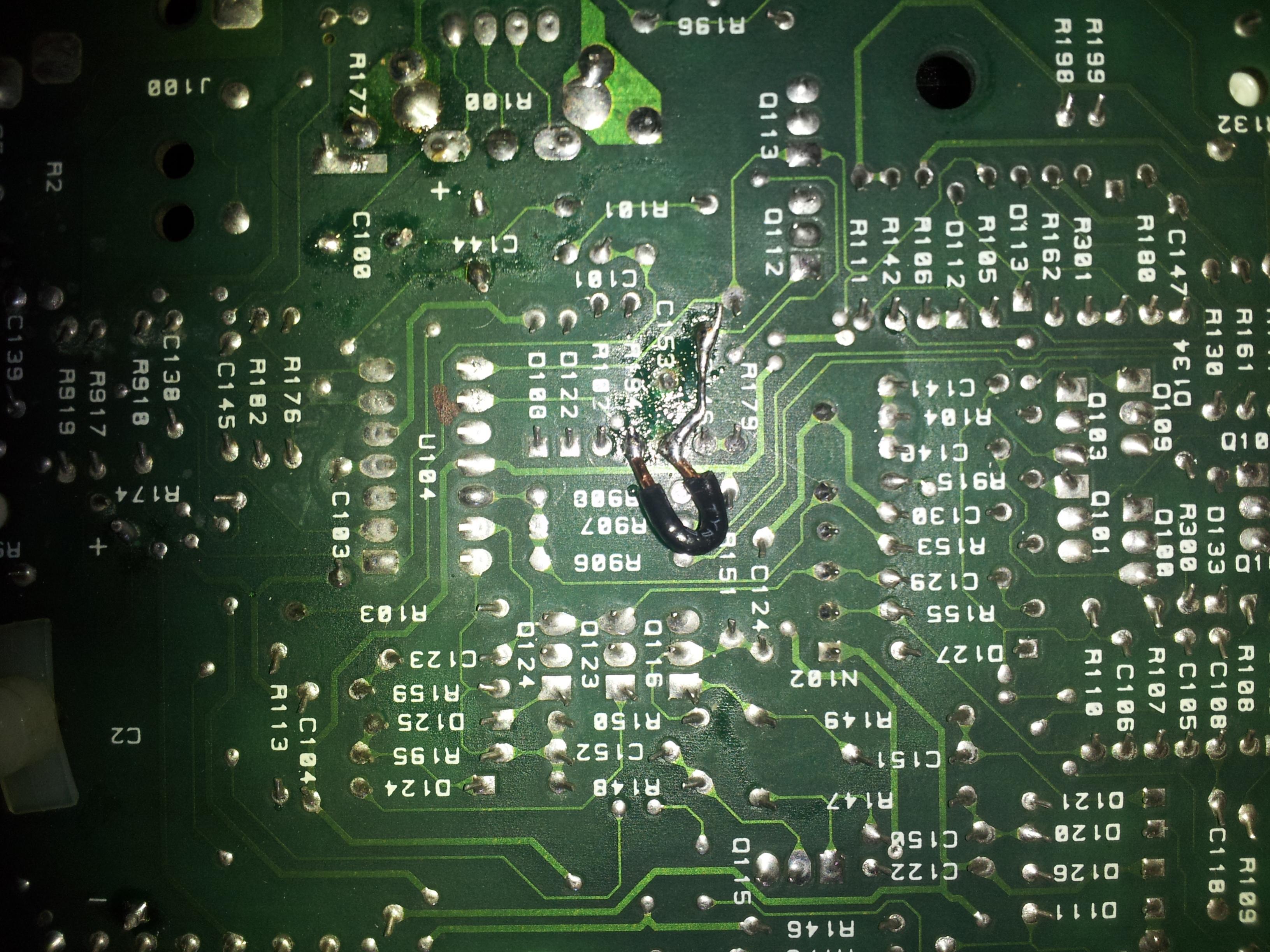
Notice C153 in F10. I believe that I pulled up the contact pad on the side of C153 that contacts c146, q112, r102, and r194.
At first, I simply bridged R194 and C153 (not realizing that I also needed to bridge the capacitor to c146).
I turned on the amp and I noticed that the yellow IOC light was on solidly while the ODEP and SPI indicators were flashing intermittently. I turned off the amp after a few seconds and reexamined my work. Without thinking, I believed that I needed to bridge c146 and c153 instead so I did that while removing the bridge from r194 and c153.
Obviously, the yellow ioc light turned on again and the the other two lights flashed. I was perplexed until I figured out that I needed to run bridges to both C146 and R194. After doing so, I double checked my work, turned on the amp again and saw that the yellow IOC light was off!
Here is a picture of my final soldering work:
I was thinking that everything would be great, so I ran through checks 1 and 2 on the service manual.
http://www.crownaudio.com/pdf/legacy/ct400sm.pdf
Surprisingly, the output bias was only 180 mv on both R31 resistors so I adjusted R26 on both channels until the output bias was 310 mv on both R31s.
Satisfied with my work for the evening, I put the case back on the amp and wired her up. I put on some Toto and realized that I wasn't getting any sound from channel 1... I checked all of my speaker wires and saw that there weren't any problems there....
In case I shorted out the Lme opamp on channel 1, I removed it and reinstalled the old opamps. I also rechecked the output bias on both channels and saw that it had increased to 550 mv on R31 on channel 1. I then adjusted it down to 320 mv.
Finally, I turned on my amp again but still I did not hear any music from channel 1. This time however, I was getting some static from channel 1 instead. I checked my other soldering joints on the board and they appear to be fine.
Anyway, if you have any guess at all as to what my problem might be, please let me know. I hope that I haven't destroyed this awesome amp for good!
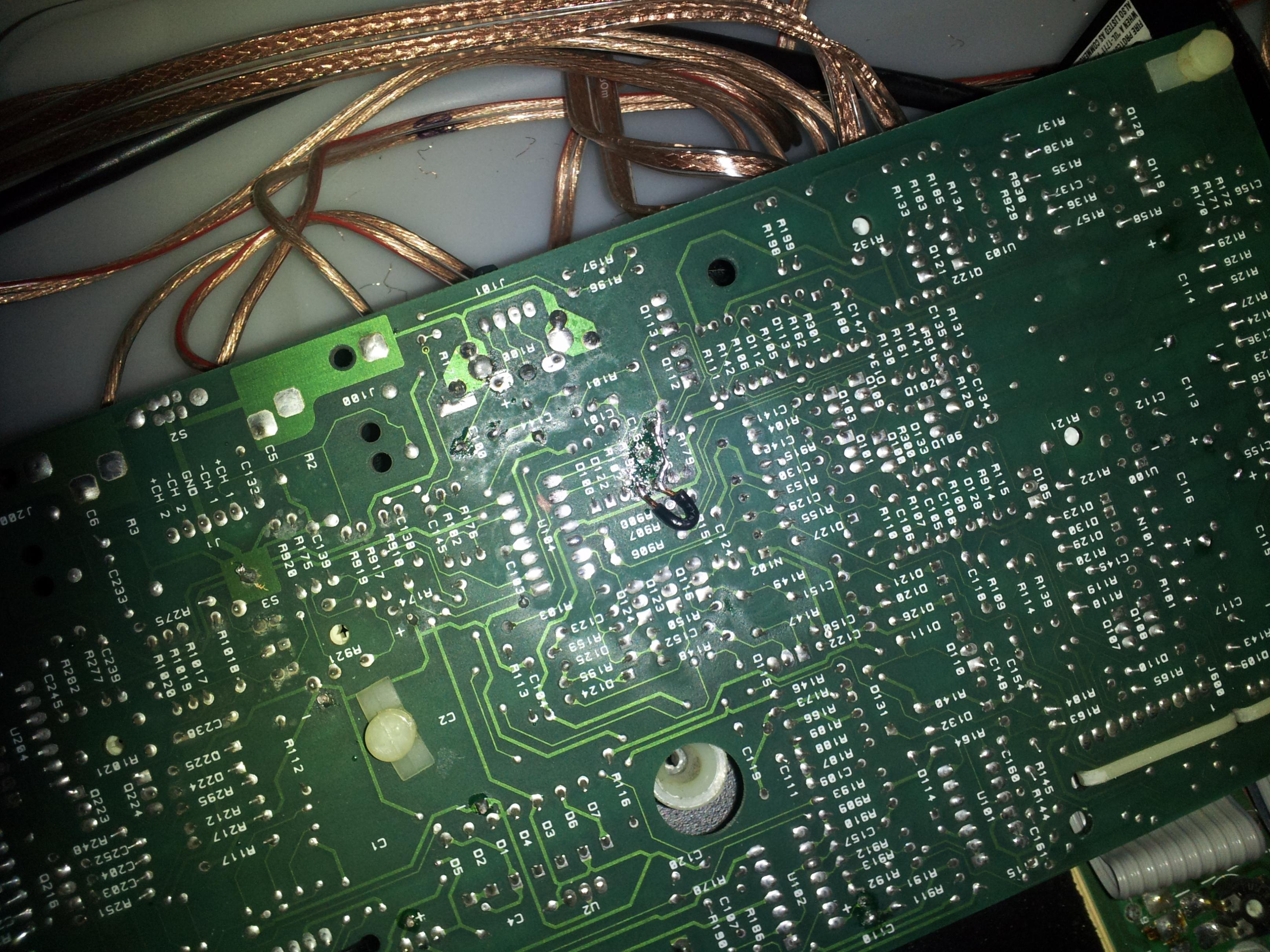
Here is another picture of the input board:
Thanks
Not wanting to stop there, I asked about a few upgrades that can be done (like swapping capacitors, etc.) and DJK told me to look at adding a parallel .1uf capacitor on c100 and a nice film capacitor on c153 (in addition to adding a 22uf capacitor in parallel with each large 6300uf capacitor).
DJK was more than helpful. I want to say here that everything following is related to some stupid mistakes that I made, not anything that he suggested.
Here is my first thread:
http://www.diyaudio.com/forums/solid-state/196005-crown-com-tech-400-dead-channel.html
I did some research myself and determined that the National lme49740na should be a good drop-in replacement for the stock MC33709 opamps. Yesterday, I threw in the new opamps (dip 14 socket packaging) and began replacing capacitors.
Anyway, I was almost done replacing the remaining electrolytic capacitors on the input board (C110, C210, C100, C200, C153, C253) and adding parallel .1uf capacitors to C100 and C200 when I managed to pull the solder contact pad off of one of the ends of C153. I began to freak out, however I calmed myself down and looked at the schematic.
http://www.crownaudio.com/pdf/legacy/ct400_main.pdf
Notice C153 in F10. I believe that I pulled up the contact pad on the side of C153 that contacts c146, q112, r102, and r194.
At first, I simply bridged R194 and C153 (not realizing that I also needed to bridge the capacitor to c146).
I turned on the amp and I noticed that the yellow IOC light was on solidly while the ODEP and SPI indicators were flashing intermittently. I turned off the amp after a few seconds and reexamined my work. Without thinking, I believed that I needed to bridge c146 and c153 instead so I did that while removing the bridge from r194 and c153.
Obviously, the yellow ioc light turned on again and the the other two lights flashed. I was perplexed until I figured out that I needed to run bridges to both C146 and R194. After doing so, I double checked my work, turned on the amp again and saw that the yellow IOC light was off!
Here is a picture of my final soldering work:
I was thinking that everything would be great, so I ran through checks 1 and 2 on the service manual.
http://www.crownaudio.com/pdf/legacy/ct400sm.pdf
Surprisingly, the output bias was only 180 mv on both R31 resistors so I adjusted R26 on both channels until the output bias was 310 mv on both R31s.
Satisfied with my work for the evening, I put the case back on the amp and wired her up. I put on some Toto and realized that I wasn't getting any sound from channel 1...
I checked all of my speaker wires and saw that there weren't any problems there.... In case I shorted out the Lme opamp on channel 1, I removed it and reinstalled the old opamps. I also rechecked the output bias on both channels and saw that it had increased to 550 mv on R31 on channel 1. I then adjusted it down to 320 mv.
Finally, I turned on my amp again but still I did not hear any music from channel 1. This time however, I was getting some static from channel 1 instead. I checked my other soldering joints on the board and they appear to be fine.
Anyway, if you have any guess at all as to what my problem might be, please let me know. I hope that I haven't destroyed this awesome amp for good!
Here is another picture of the input board:
Thanks
Attachments

Last edited:
Hi,
I think you should use a cleaner and clean the area were you solder the wire. Second why use a wire so heavy. Next time find a stranded wire and remove one and use it to solder the copper run. Right now I do not think that copper run is solder right. Normally I use acetone to clean the rosin that left when you solder.
I think you should use a cleaner and clean the area were you solder the wire. Second why use a wire so heavy. Next time find a stranded wire and remove one and use it to solder the copper run. Right now I do not think that copper run is solder right. Normally I use acetone to clean the rosin that left when you solder.
Tauro,
Thanks for the tips, but I cleaned all of the rosin off with isopropyl alcohol and then continuity checked all of those points. They all show no resistance on my volt meter. I also checked the connections on these components on the top side of the pcb and everything appears to be hooked up as I described.
I wonder if this wiring issue damaged something else on the pcb?
Last edited:
I can't help with Your initial problem, but i noticed in your first picture, that you have at least two cracking solderings at R176 and R182.
May not be a problem right now, but it will eventually create more trouble.
I wish you good luck.
Best regards Ebbe
Es, thanks for the sharp vision. I got those points re-flowed so that they will no longer pose any problems. I'll have to take a high resolution photo to see if I can spot any other problems.
Also, I removed the parallel capacitors from the input board and replaced the new .1uf 100v capacitor on c153 with the older .1uf 50v capacitor. I turned on the amplifier and still I could not hear anything except for static coming from channel 1.
I also noticed that the sound indicator light flashes with the music on channel 2. It almost seems like the signal for channel 1 isn't even making it to the amplifier. I swapped the inputs from my computer to check this and I still didn't get any sound.
I wonder if something got fried closer to the inputs. I'm not good enough at reading a schematic like this to even start testing components.
The first rule of audio is if it works leave well alone ! boring but true lol
Its easy to destroy multiple components with a mistake, then a simple job turns into a massive debugging exercise.
That pcb has some very light traces so I am not surprised you lifted a pad.
I would never have disturbed it.
Its easy to destroy multiple components with a mistake, then a simple job turns into a massive debugging exercise.
That pcb has some very light traces so I am not surprised you lifted a pad.
I would never have disturbed it.
Hi,
Did you check the +15/-15 that goes to IC104C? Also can you check the voltage output pin 8. If it is possible compare it with the good one.
Regards,
tauro0221
Tauro,
I checked those voltages and everything appears to be normal. I am getting +15.30 volts from both channels and -15.00 volts from both channels (using my cheap volt meter). This was measured at the point of origin for both.
I don't know about output pin 8. It seems that both opamps should be facing the same direction, however the opamp for channel 2 (IC204) is wired in 180 degrees from the opamp in channel 1 (IC104).
In other words, pin 8 for IC104 is connected to a different part of the pcb than pin 8 for IC204. It seems that pin 8 on IC204 is putting out the same voltage as pin 8 on ic104, just to another trace on the circuit.
Could it be that I flipped the opamp on channel 1 around? I lined it up with the indent indicator on the pcb and I swear that I remember both opamps facing the same direction before I upgraded them....
Do you think that I should flip the opamp for channel 1 around and try to see if I get any audio?
I don't want to damage anything else so I might hold off until I get more confirmation!
Nigel,
Thanks for the tip but rest assured that I will put this amp away and never touch it again if I do manage to save it! I made that decision before I even posted on here lol.
Thanks again.
Last edited:
Sorry, please ignore my last comment on the pin 8 problem. I read note 3 on the schematic.
Pin 7 is the voltage output pin on channel 2.
Here are the voltages for pin 8/7 while playing music.
Pin 8 on channel 1: .009 volts
Pin 7 on channel 2: .070 volts
Why would pin 8 on channel 1 only be putting out 1/7th the voltage of pin 7? What do you think I check out now?
Thanks
Pin 7 is the voltage output pin on channel 2.
Here are the voltages for pin 8/7 while playing music.
Pin 8 on channel 1: .009 volts
Pin 7 on channel 2: .070 volts
Why would pin 8 on channel 1 only be putting out 1/7th the voltage of pin 7? What do you think I check out now?
Thanks
Last edited:
I think the only way to check this channel is using an scope. Input a sine wave signal and goes through the signal path.
Both pin should read close. Try putting a signal on both channel and compare the reading. This is the first stage of the amplifier. If this op amp is not working you will not heard anything in the output.
Both pin should read close. Try putting a signal on both channel and compare the reading. This is the first stage of the amplifier. If this op amp is not working you will not heard anything in the output.
Tauro,
I don't have an oscilloscope, however if necessary I will purchase one to diagnose the problem.
I was testing everything near pin 9 and the area where I repaired C153 and I noticed that diodes D108 and D122 are acting strangely. When tested one direction with my diode tester, they read about .6 volts. When tested the other way though, they kept fluctuating between .6 volts and infinite resistance.
When I tested D208 and D222, both read .6 volts in both directions consistantly... which is odd in itself!
Here is the diode part number from the Crown parts directory:
C 3181-2 DIODE, 0.3A 75V 1N4148 AXL
Shouldn't these diodes only conduct one way with a constant voltage?
Hi,
The diode when the neg lead is in the cathode and the red in the anode should read .6. When reverse the lead should read infinitive. This is when tested outside the circuit. Did you read the diode in place? To get a good reading you have to lift one side from the circuit board.
The diode when the neg lead is in the cathode and the red in the anode should read .6. When reverse the lead should read infinitive. This is when tested outside the circuit. Did you read the diode in place? To get a good reading you have to lift one side from the circuit board.
Hi,
I have some questions. Did you removed the U104? Did you mounted it in a socket? How good you removed it? When you remove an IC you have to very careful because if not you may damage the traces and some time removed the feed thru of the eyelets. Another thing this U104 is critical because it had 4 operational amplifiers. Follow U104a, U104b, U104c and U104d in the schematic and you would see they are used in the preamp and one is used in the low pre driver location F2. So you need to make sure is working good or nothing work in the amplifier
I have some questions. Did you removed the U104? Did you mounted it in a socket? How good you removed it? When you remove an IC you have to very careful because if not you may damage the traces and some time removed the feed thru of the eyelets. Another thing this U104 is critical because it had 4 operational amplifiers. Follow U104a, U104b, U104c and U104d in the schematic and you would see they are used in the preamp and one is used in the low pre driver location F2. So you need to make sure is working good or nothing work in the amplifier
Tauro,
U104 actually came mounted in a socket. Otherwise, I definitely would not have swapped it out! I just removed u104 and replaced it with the National LME49xxx opamp which has 4 operational amplifiers like the original chip.
I replaced u204 with a national lme49xxx opamp as well and channel 2 works fine.
To make sure that the national opamp wasn't causing the problem, I swapped in the original MC33xxx opamp and I noticed a difference. Instead of hearing nothing from channel 1, I heard static from channel 1! Obviously, the problem is located somewhere around U104.
Should I reflow the solder on all of the contacts for U104? Could I have damaged something removing the opamp from the socket? I didn't remove the socket.
Thanks
Last edited:
I wish that this forum allowed for edits after a period of time lol.
I checked the DC offset at the channel 1 output connectors and my voltmeter reads 200 mv even though it should read 0. The service manual says that if dc offset is out of spec that this would indicate that u104 is out of tolerance. Note that I saw this with the MC33xxx installed.
Edit: I also was able to get some sound from channel 1. It gave me static that was "in sync" with the music that I was playing.
Last edited:
Since looking back on how the problem started was when you removed the C153 capacitor. It is possible that a traces it is still open. Capacitor C153 is connected to U104.
I have a suggestion. It is a tedious one but it will tell you if everything in the U104 it is OKAY. With the ohmmeter check each pin by touching the IC pin and the other one to a component that the pin is connected. Example U104 pin 8 is connected to R113,R179 and Q113. With one lead of the meter at pin 8 and the other lead to the R113 side connected to pin 8. See if you have conductivity between them. Do the same test with the other pins. This test will tell you if you have a good connection between the U104 and the traces on the board with the other components.
I have a suggestion. It is a tedious one but it will tell you if everything in the U104 it is OKAY. With the ohmmeter check each pin by touching the IC pin and the other one to a component that the pin is connected. Example U104 pin 8 is connected to R113,R179 and Q113. With one lead of the meter at pin 8 and the other lead to the R113 side connected to pin 8. See if you have conductivity between them. Do the same test with the other pins. This test will tell you if you have a good connection between the U104 and the traces on the board with the other components.
Since looking back on how the problem started was when you removed the C153 capacitor. It is possible that a traces it is still open. Capacitor C153 is connected to U104.
I have a suggestion. It is a tedious one but it will tell you if everything in the U104 it is OKAY. With the ohmmeter check each pin by touching the IC pin and the other one to a component that the pin is connected. Example U104 pin 8 is connected to R113,R179 and Q113. With one lead of the meter at pin 8 and the other lead to the R113 side connected to pin 8. See if you have conductivity between them. Do the same test with the other pins. This test will tell you if you have a good connection between the U104 and the traces on the board with the other components.
Tauro,
I spoke with Crown support today and Kevin looked at the input circuit again. We determined that there might be more components on the input board than are on the schematic because this schematic is from 1990 and my amplifier is from 1996.
Since the IOC lights are not coming on, all of the components are functioning but there is likely some part of the circuit that is open (ie something still isn't connected). Hopefully this new 1996 schematic will reveal something new.
Thanks again for the help.
Last edited:
I was psyched until I received the correct schematic lol. It doesn't seem like there is any difference between the original 1990 schematic and the 1994-1996 schematic in this area.
Do you see anything that could be related to the problem that I'm experiencing?
Here is the correct schematic:
J0631-2_D.pdf
Thanks
Do you see anything that could be related to the problem that I'm experiencing?
Here is the correct schematic:
J0631-2_D.pdf
Thanks
- Status
- This old topic is closed. If you want to reopen this topic, contact a moderator using the "Report Post" button.
- Home
- Amplifiers
- Solid State
- Oh Shoot! Did I Kill a Channel?