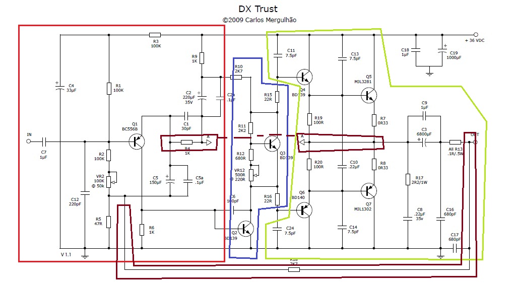
Well...... This is DX Trust amp Special ones.
I also attached a picture of grounding method, or others also.
Most of the article i saw today, is only mentioned grounding with dual supply, no single rail, which lead me hard to decide what to do.
The main cause of the confusion is the negative serve as both negative rail, and grounding, so some matters i learn in dual supply grounding have collision. (2 direction of information)
I will give some example :
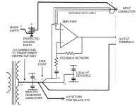
This is the consideration of the star ground, should I arrange the position of ground connection ? From the quote, the sequence is Power supply>Output stage>Rest of the amplifier, which applies to V+. But what about negative/ground ?the best method is to bring the rails up to the output stage from one side, with the rest of the amplifier on the other side. Then run tracks from the output to power the rest of the amp; these carry no halfwave currents and should cause no problems.
Minimise pickup of rail radiation by keeping the area of the input and feedback circuits to a minimum. These form loops with the audio ground and these loops must be as small in area as possible. This can often best be done by straddling the feedback and input networks across the audio ground track, which is taken across the centre of the PCB from input ground to output ground.
Should it be PS>Output transistor >Output Grounding(C8,C16,C17) >Q2 emitter >Star Point(dividing) >(i)input ground+feedback ground, (ii)Decoupler(C18, C19), (iii)Speaker negative Terminal (iv) input stage negative (R5, R6, C12) ?
Or should position of Q2 connection and input negative change a bit ?
So should I running my ground and V+ together ?Minimise radiation from the supply rails by running the V+ and V− rails as close together as possible.
The same problem arises with most valve circuits. Two common solutions there are bus or star grounding. The main thing is to keep PSU charging pulses well away from the signal ground, and keep output currents well away from input circuitry. The tricky bit with single-rail transistor circuits is sorting out the speaker ground connection, because the current has to return to the PSU -ve but the feedback should be referred to the clean signal input ground. This particular problem is easier with valves because the OPT secondary provides isolation, although there is still scope for people to get it wrong.
Well.... words are hard to express my idea, so i draw
Hm.... just for clearance, according the typical grounding diagram, which is the feedback ground ? (R5/R6/C12 ?)
In my drawing, the right of star point is the audio ground, which contain all the sensitive circuit, and which is the most sensitive ones ? (is it my drawing correct ?)
Below the star point is the Decoupler, which may contain sub-heavy ripple. Should i put it further front(nearer to power supply) to improve, such as before the Q2 ?
I personally felt that the Q2 need to connected to star(behind), is my intuition correct ?
What does C8, C16, C17 does, and what kind of current they pass on ? (will it fluctuate the input if placed near ?)
Attachments
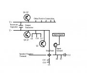

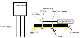
I think of a new idea, if i make use of a very short wire (lesser than 0.5cm), then connect the output device with the PCB through wire, thus make it almost connect to the board, but provide flexibility to change the position of the transistor. (not stiff, but able to flex above the out device with little tolerance)
Another new idea, is to direct the power supply (after reservoir Cap), to the output device at the middle of the pin, then at the end of the pin are to connect supply other component.
Well.. its hard to understand sometimes, so i attached a drawing of mine, the gray color is the short flexible wire (stranded wire). Does this a good idea ?
This idea easily fulfill the guideline of this :
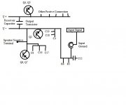
So the output is far from the supply (as far as possible), and also can power the rest of the amplifier.Minimise radiation from the supply rails by running the V+ and V− rails as close together as possible. Keep them away from the input stages of the amplifier, and the output connections; the best method is to bring the rails up to the output stage from one side, with the rest of the amplifier on the other side. Then run tracks from the output to power the rest of the amp; these carry no halfwave currents and should cause no problems.
Attachments
No, you are creating future problems for yourself. Treat device leads as part of the device. Self's advice should guide your PCB design, and overall wiring.
Bear in mind that the connections to any Class B output device carry highly distorted signals. It is only where they join the other half that you have a normal signal.
Bear in mind that the connections to any Class B output device carry highly distorted signals. It is only where they join the other half that you have a normal signal.
what about using flexible wire to connect with very short type ? (0.5cm) for flexibility ?
How do they join, at where ? can briefly describe ?It is only where they join the other half that you have a normal signal.
So in short i need to make those minimum length ?Bear in mind that the connections to any Class B output device carry highly distorted signals.
They join at R7/R8, to form the output voltage. The leads/PCB tracks/wires connecting to the output devices will carry distorted current (almost like half-wave rectified signals). You can't always keep them short because the PSU may be at the other end of the box. What you can do is keep them well away from other things, and ideally close together (even twisted) so that the magnetic field has contributions from both halves of the waveform and so is less distorted.
Hi
I suggest you use a suitably rated bridge rectifier join its negative and positive outputs together send that to chassis ground, and then have one of the AC inputs for power related ground and the then other AC input for signal ground.
If necessary one of these bridge rectifiers per channel.
Cheers / Chris
Cheers / Chris
hm.... get it ! but most probably the output lead will be in PCB, so twisting is out of question.
But if i were to keep it(distortion) from that away from the amplifier, how much space should i leave from the output path to other circuitry ? (My amplifier lower than 30W rms)
Chris - I can't understand some of it
What do you mean by
But if i were to keep it(distortion) from that away from the amplifier, how much space should i leave from the output path to other circuitry ? (My amplifier lower than 30W rms)
Chris - I can't understand some of it
I understand that the bridge rectifier for output, then i only connect it to the chassis ground, not the speaker terminal ? What is the purpose and function ?and then have one of the AC inputs for power related ground and the then other AC input for signal ground.
What do you mean by
?We haven't yet got to the issue of safety vs. signal grounds. That will crop up later.
X.x douglas said the opposite ?The link from A to B in your picture from post 2 is the connection between signal and safety ground. This can introduce a hum loop. Including a beefy bridge rectifier here is one way to maintain safety grounding while breaking the hum loop.
If i didn't misunderstood your meaning, the safety ground is the main voltage ground.Connecting mains ground to starpoint is better, as the charging pulses are excluded, but the track resistance between input ground and star will carry any ground-loop currents and induce a buzz. Connecting mains ground to the input ground gives maximal immunity against groundloops.
hm...... still not understand about the layout, have any picture, or diagram for my as reference ? (how to connect the grounding rectifier)
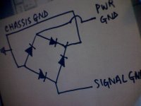
A Diagram as requested, it shows Power Ground and signal ground having separate paths to Chassis Ground and in the process not mixing together
Or the AC inputs can be instead Left and Right signal grounds, in which case then connect your power ground returns direct to chassis. Give it a try it usually quietens down most ground problems. Recommend a 35 amp potted bridge 1000v
Cheers / Chris
Or the AC inputs can be instead Left and Right signal grounds, in which case then connect your power ground returns direct to chassis. Give it a try it usually quietens down most ground problems. Recommend a 35 amp potted bridge 1000v
Cheers / Chris
Attachments
Last edited:
wow..... 35Amp... need so much ? since my speaker only less than 30W at 40V. what do you mean by POTTED bridge ?
what do you mean by "Or the AC inputs can be instead Left and Right signal grounds, in which case then connect your power ground returns direct to chassis."
The Power ground you written is means power supply ground, or power(output) stage ? Or just others than input&feedback ground ? (signal ground is input and feedback ground ?)
The bridge in the ground lift must be able to bear full short-circuit mains current without vapourising itself for as long as it takes for the breaker to trip or the fuse to blow. A 35amp bridge can probably cope with a few hundred amps for a few seconds. If it shorts out then even better!
- Status
- This old topic is closed. If you want to reopen this topic, contact a moderator using the "Report Post" button.
- Home
- Amplifiers
- Solid State
- Grounding on single rail ? (building aspect)