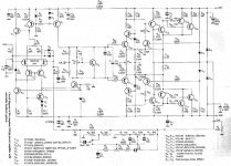
I found this design in an old magazine. It is by Yuri Ezhkov and was published in Electronics World of September 1999 under the title "Fast Audio Power." The circuit diagram is attached to this post. If there is any interest I can post the other two pages.
The design is quite complicated. I have to admit that I have yet to get my mind into high gear to figure it all out.
The specifications given includes output power is 90W into 4 ohm with a slew rate better than 50V/us. Although the author gives some detail of construction in the text, there was no PCB design.
I don't know if any of the ideas presented went any further. The design uses a bewildering number of different transistors. The author does give alternative type numbers for most of them, but it does not help much as they are not familiar to me. What makes it worse is that I do not have a SPICE model for even one of them. Simulating this design will therefore be quite undertaking.
Attachments
Last edited:
This is not a SOTA design.
I'd skip it and take the advice above on Cordell and Self. For more practical and closer to home examples, see OStripper's work on this forum (at the top of the page). This will deliver high slew rates, ultra low distortion in a very practical and down to earth design and uses many of Self and Cordell's techniques.
I'd skip it and take the advice above on Cordell and Self. For more practical and closer to home examples, see OStripper's work on this forum (at the top of the page). This will deliver high slew rates, ultra low distortion in a very practical and down to earth design and uses many of Self and Cordell's techniques.
Hi, Bonsai , that s quite right, but with some limitations.
The usual LR output circuit almost invariably save the day with most
designs that are instable as soon as some capacitive loading is added,
and it will be more than mandatory in those so called high slew rate designs,
partly reducing the expected SR...
As for full symetrical circuits , unfortunately they dont work as easily
as the single differentials , but they have the advantage of better stabilty
as well as symetrical slewing.
Thanks for all of the input, guys. To advance the state of the art, we have to keep looking at all the alternatives out there.
The Blameless design is certainly the one to go for if you want something that will work, and work well. I have one on the back burner at the moment.
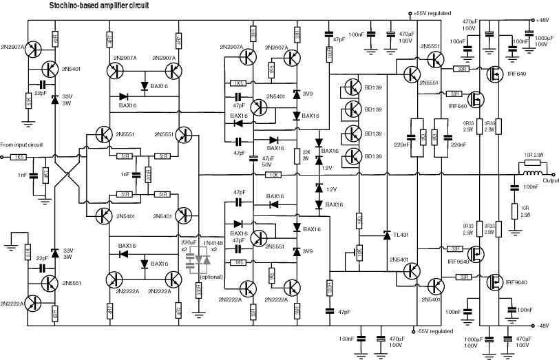
I will look at the Stochino design. Is this the definitive version?
The Blameless design is certainly the one to go for if you want something that will work, and work well. I have one on the back burner at the moment.
I will look at the Stochino design. Is this the definitive version?
Yes, be sure to upgrade the output mosfets, those are not really capable for the power rating of that amp. When pushed hard into 4 ohm loads those will go up in smoke.
Youll need a very good pcb design too, if you dont get it right, those mosfets will go up in smoke too.
BTW, ingenious where you from??
Youll need a very good pcb design too, if you dont get it right, those mosfets will go up in smoke too.
BTW, ingenious where you from??
You could change all of the diodes from BAX16 to BAW62. Homemodder should be able to tell you more, but there are some who have changed the input transistors and driver transistors to faster types and heard greater transparency. I have the unmodded Stochino and have yet to try changing transistor types.
Going back to the original post, the reason for the high speed aspect of the design is that several stages are held at a constant output voltage, so they avoid Miller capacitance slowdown. The input goes to p-channel JFET's whose outputs are Tr4 and Tr5 emitters which have their base voltages fixed. Thus, the emitter voltages will be fixed at one diode drop above that. The JFET's have a certain amount of gate-to-drain capacitance. In a typical amplifier, the drain varies in voltage in the opposite direction to the gate, causing the gate-to-drain capacitance to be multiplied by the gain. The extra voltage across the capacitor causes the current through the capacitance to increase by the value of gain+1 and thus, the capacitance appears to be greater than it is. This is the Miller capacitance. It acts to reduce bandwidth and slew rate. By preventing the drain voltage from moving, the Miller capacitance factor goes from gain+1 to 1, a substantial reduction.
The design shows this again on Tr10 and Tr12 and also Tr 11 and Tr13. This is a cascode connection where the collector voltage of the bottom transistor (Tr10 and Tr11) is held constant by the fixed emitter voltage of the upper transistor. This also prevents the Miller capacitance factor from being any larger than 1 (whereas it would be gain+1 without the upper transistors). The use of cascode stages (a common source or emitter stage feeding a common base stage) helps improve the high-frequency response and increase slew rate.
The design shows this again on Tr10 and Tr12 and also Tr 11 and Tr13. This is a cascode connection where the collector voltage of the bottom transistor (Tr10 and Tr11) is held constant by the fixed emitter voltage of the upper transistor. This also prevents the Miller capacitance factor from being any larger than 1 (whereas it would be gain+1 without the upper transistors). The use of cascode stages (a common source or emitter stage feeding a common base stage) helps improve the high-frequency response and increase slew rate.
The things you talk about above do not affect the speed (i.e. slew rate) of an amplifer.
The slew rate is set by the LTP tail current and Cdom in a conventional arrangement and nothing else.
On an FBS topology design, it is quite easy to get 100V/uS (and be stable). All you have to do is ensure that the tail current is high enough to slew the comp cap fast enough in order to acheive this rate of change.
If you use some of the more esoteric approaches (see Bob Cordell's book for a definitive discussion on this), you can achieve 2-3 times this rate (and be stable).
Note also, the UG frequency is set independently of the tail current from Cmiller= 1/[2Pi*fc*Rltp*Acl). The bandwidth is set by the input stage gm and Cdom.
The specifications given includes output power is 90W into 4 ohm with a slew rate better than 50V/us. Although the author gives some detail of construction in the text, there was no PCB design.
It seems to me that any discussion of slew rate needs to be grounded in what we are trying to do. Required slew rate increases with frequency, and also with peak voltage. At a constant power output you need more voltage as impedance goes up, and as a result a higher slew rate. The article at the link below has a handy table that relates this to amplifier power and speaker impedance. To reproduce a 20 kHz sine wave requires a slew rate of about 3.5 V/uS to feed 90 watts into 4 ohms. This makes me wonder if a slew rate of 35 would be as useful as a bandwidth of 200 kHz instead of 20 kHz in audio applications?
Slew Rate Technical Notes
It also makes me wonder as the human ear especially after the age of 35 is limited to at best 10khz if a bandwith of 200khz is useful. Good questions.......
As is, the 300Vus amp by stochino sounds excellent to me and many high end companies and myself prefer video opamps which have high slewrates albeit Ill admit these usually also have high bandwith.
- Status
- This old topic is closed. If you want to reopen this topic, contact a moderator using the "Report Post" button.
- Home
- Amplifiers
- Solid State
- The high slew rate design that time forgot?