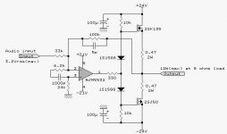
The 2sj50 is shown upside down.
These are Lateral mosFETs. Diodes seem an odd choice for generating the bias voltage.
This is an inverting topology. Is that what you want?
Maximum output is specified as 13.7Vpk.
Using +-24Vdc supplies for only 13.7Vpk seems odd.
No gate resistors.
DC coupled
This looks more like a "test" for students, "work out want is wrong and give your solutions".
The 2sj50 is shown upside down.
These are Lateral mosFETs. Diodes seem an odd choice for generating the bias voltage.
This is an inverting topology. Is that what you want?
Maximum output is specified as 13.7Vpk.
Using +-24Vdc supplies for only 13.7Vpk seems odd.
No gate resistors.
DC coupled
This looks more like a "test" for students, "work out want is wrong and give your solutions".
All agreed. Plus I doubt that the voltage drop across the 2 diodes would be enough to make it other than pure class B.
The rails to the op amp are a lower 21V BTW.
This looks more like a "test" for students, .
Andrew, this is old schematic from "Electronic-Life" Vol.12, 1988 [12w Fet Power Amplifier by Sakasegawa
- Status
- This old topic is closed. If you want to reopen this topic, contact a moderator using the "Report Post" button.