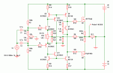
I had my eyes on this topology for the last six months. I know I will do good to go with F5, the thing is that I just don't like common source output stages. No offence, I am sure it sounds GREAT to many people. Also I have no prior experience with JFET inputs and symmetrical current-source amplifiers (more the reason why I should try F5  ).
).
So I (poorly) designed this circuit from gathered information from the net(took quite a lot of on-screen reading, ufffff). It's simple to look at but gave me nightmares while setting the offset. A little more reading and found the trick.
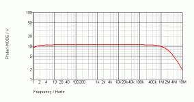
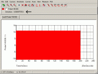
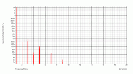
The input BJTs are biased at ~10mA, VAS at ~50mA and FETs at ~1A. After playing with the resistor values I have found this config to have a sim-ed distortion of 0.0089% @ 1KHz / 20V P-P output without too much dissipation in the transistors. This value seems good but I believe the resistor values are still not optimum and circuit performance can be increased even more. I have seen that a higher bias in the input and VAS stage gives a larger bandwidth but the output shows oscillation(too much phase-shift may be) after the bandwidth exceeds 10MHz. This is at a current of 20mA and 120mA in the input and VAS respectively. Of course the devices will die out of excessive dissipation at these currents. With the shown values the bandwith is ~1.9MHz.
I know I can eliminate the input caps by using buffers, but that would require at least ten more solders joints and I am short on space. MKT at inputs are perfectly OK for me, besides I am prejudiced that they sound good . I got all the parts minus the offset-ing pot, so am quickly going to place them on veroboard.
Althought the simulation showed excellent even harmonic cancellation and overall very low distortion I'm pretty sure real life is going to be a different story. Will use 2SK/2SJ laterals from hitachi as the output FETs. Plan to run at +-35V@1A in future if this 20V thing survives. I still don't have an o-scope, monitoring the bias and voltage differences are my only way to be ensured of stable operation. Any creative suggestions on design improvement(without increasing complexity too much) are welcome.
Please remember, this is a poor design and I am a total ameteur. So please don't confuse me with sophisticated computational stuff. I want to make an amplifier and have fun bulding/listening to it. It needn't measure super; if it doesn't sound good after all, then I'll just dump it into my archives. Peace.
So I (poorly) designed this circuit from gathered information from the net(took quite a lot of on-screen reading, ufffff). It's simple to look at but gave me nightmares while setting the offset. A little more reading and found the trick.
The input BJTs are biased at ~10mA, VAS at ~50mA and FETs at ~1A. After playing with the resistor values I have found this config to have a sim-ed distortion of 0.0089% @ 1KHz / 20V P-P output without too much dissipation in the transistors. This value seems good but I believe the resistor values are still not optimum and circuit performance can be increased even more. I have seen that a higher bias in the input and VAS stage gives a larger bandwidth but the output shows oscillation(too much phase-shift may be) after the bandwidth exceeds 10MHz. This is at a current of 20mA and 120mA in the input and VAS respectively. Of course the devices will die out of excessive dissipation at these currents. With the shown values the bandwith is ~1.9MHz.
I know I can eliminate the input caps by using buffers, but that would require at least ten more solders joints and I am short on space. MKT at inputs are perfectly OK for me, besides I am prejudiced that they sound good
 . I got all the parts minus the offset-ing pot, so am quickly going to place them on veroboard.
Althought the simulation showed excellent even harmonic cancellation and overall very low distortion I'm pretty sure real life is going to be a different story. Will use 2SK/2SJ laterals from hitachi as the output FETs. Plan to run at +-35V@1A in future if this 20V thing survives. I still don't have an o-scope, monitoring the bias and voltage differences are my only way to be ensured of stable operation. Any creative suggestions on design improvement(without increasing complexity too much) are welcome.
Please remember, this is a poor design and I am a total ameteur. So please don't confuse me with sophisticated computational stuff. I want to make an amplifier and have fun bulding/listening to it. It needn't measure super; if it doesn't sound good after all, then I'll just dump it into my archives. Peace.
Attachments
Last edited:
Looks abit like a current feedback opamp. You should be able to stabalise it by introducing a capacitor from the left side of R13 to ground, this will decrease open loop the high frequency gain. Show the open loop frequency response, this thing sounds like it might be close to the edge...
If your looking for some reading matter try:
http://www.analog.com/static/import...tes/58052492001115525484056221917334AN211.pdf
If your looking for some reading matter try:
http://www.analog.com/static/import...tes/58052492001115525484056221917334AN211.pdf
Thanks for your comment kipman.
I have already read that App note. I initially did add that cap, closed loop BW was 1.1MHz. I didn't like the idea(another cap?!). So I removed it, added a lot of degeneration resistors which reduced the BW from 10MHz to 1.9MHz. Yes, 10MHz is without degeneration. Totally unstable.
I have already read that App note. I initially did add that cap, closed loop BW was 1.1MHz. I didn't like the idea(another cap?!). So I removed it, added a lot of degeneration resistors which reduced the BW from 10MHz to 1.9MHz. Yes, 10MHz is without degeneration. Totally unstable.
Some more plots:
Open loop gain:- 63dB
Open loops BW:- 10KHz
Important point: Phase shift of -180degrees occur at 15MHz, but at 15MHz closed-loop gain is still above unity. Solved this by increasing the degenerations resistors at the emitters of the VAS from 22ohm to 33ohm. As a result current through VAS is 35mA(15mA down) and unity gain frequency is now 10MHz at -125degree. The distortion graph seems unaffected by this modification. But FET bias setting needed re-setting(obviously).
Hmm... I don't have 33ohm at stock.
And so, I am going to try this amp with 22ohm as was before. Looking forward to stray board-capacitance come into act for this. Even 1pF will do! Otherwise 33ohm.
- Status
- This old topic is closed. If you want to reopen this topic, contact a moderator using the "Report Post" button.


