I have not used that one but the relay specifications look reasonable. I can not really say however since I have not used or tested it.
From the same vendor I see one that is opto-isolated. I would prefer to keep both channels fully independent so that the speaker returns go back to the star point. (Instead of being joined at the speaker terminals and then going back to the star point.) Again I have not used this one but I the opto-isolation looks like a good feature:
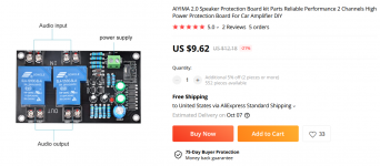
AIYIMA 2.0 Speaker Protection Board kit Parts Reliable Performance 2 Channels High Power Protection Board For Car Amplifier DIY|Amplifier| - AliExpress
Attachments
I made the connections as shown on the image, without connected to the sound source to begin with, I only connected the HP ...
a noise a bit like a turbine is emerging ...
I quickly unplugged everything, so not yet.
I find it very surprising that the screwed plug is not used for the power supply, how to check?
a noise a bit like a turbine is emerging ...
I quickly unplugged everything, so not yet.
I find it very surprising that the screwed plug is not used for the power supply, how to check?
First of all, sorry for being rude, introduce me from Indonesia, I have a quad 405 kit that is still original and if I want to get another kit to have a stereo, does anyone sell the PCB? If so, where should I order? thanks..
Do you mean a "DIY kit"? If so there are a number of different QUAD405 kits and a number of different PCB sold online. If you post a picture of the kit (PCB and parts) that you have it would be easier to see if someone recognizes that particular kit and where to buy another. There are QUAD405 and QUAD405-2 kits, for example. Then there are multiple versions such as plastic package outputs or metal TO-3.
I find it very surprising that the screwed plug is not used for the power supply, how to check?
What do you mean by "screwed plug"?


I find it very surprising that the screwed plug is not used for the power supply, how to check?
That connector actually says 'Input' on the board. It is the audio input as I outlined earlier.
If you want to check yourself then look where the connections go
")
All the connections are clearly marked and conventional.
VCC+ is the positive supply.
VEE- is the negative supply.
VOUT+ is the speaker output.
I see. Screw terminals. Those are definitely the signal input. LJM tends to use the "FASTON" metal tabs for the power supplies.
Prior to Mooly providing the wiring diagram did you apply power?
Did you apply power with the connections shown in post #194?
I am trying to figure out if it could be damaged with +/- 50V DC applied to the input. The input (film) blocking capacitors is there but you would have attached -50V to the input ground (screw terminal) and grounded the main ground FASTON.
If you did apply power like post #194 was there any smoke or smell? Is there a discolored 10 Ohm resistor?
Have you done this first? Power it all up via the bulb and check it draws only a low current and that the supplies are correct. It is very important there is no DC voltage at the speaker terminals.
I would advise you use a bulb tester to power it all up (only when you are sure it is correct) and you should check there is no DC voltage across the speaker terminals before connecting a speaker.
This is a link that I found helpful when I built my own DBT (dim bulb tester).
Powering Your Radio Safely with a Dim-bulb Tester
However for the sake of safety please make certain that you know what you are doing before you do anything with mains wiring.
I don't know if the more experienced members will agree but something else that I have done is use current limited +/-18V to +/-25V laboratory supplies or even LM317/LM337 supplies for first tests. With no speaker and no input signal a properly assembled amplifier will draw a small steady state current. If something is wrong then a good laboratory supply with current limiting will very quickly limit the current (and often light a constant current indicator).
I have one meter on the output terminals (to check for an offset/DC problem) and another meter measuring bias currents (but yes this QUAD405 is not a class-AB).
If either meter looks odd or if the supply current limits I switch it back off and investigate.
Last edited:
no, I have to tinker with thatPower it all up via the bulb and check it draws only a low current and that the supplies are correct.
Thanks Kazard for the tester link, I'll make one.
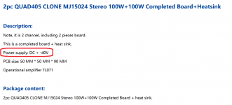
otherwise, on the seller's page:
Operating voltage: + -30V to + -50V
8R power frequency response 100W (+ -50V): dio precision 2 test data.
I don't know much about it, but don't think going over 10% voltage makes you "scream" like that
otherwise, on the seller's page:
Operating voltage: + -30V to + -50V
8R power frequency response 100W (+ -50V): dio precision 2 test data.
I don't know much about it, but don't think going over 10% voltage makes you "scream" like that
the news of the front ... I made various tests ... By reversing the polarities it does not make any more noise, but I still do not have any sound, I connected the mass of the power supply filter on the pgnd of the card and there ... little smoke, the fuse has blown ...
i will stop for today
i will stop for today
- Home
- Amplifiers
- Solid State
- QUAD 405 clone