I found some answers;
1) C8 increased to 1000uf. Bec. in ver.4, C5 increased to 33uf. (to stay in same filter freq. now nearly 0.5 hz. why decreased from 1.5hz?)
2) But, all C5,C4&C6 must be bipolar electrolytic. (1000uf bipolar?)
3) A friend said we couldn't use DC servo in this circuit, it's not suitable. Ok this is another answer.
may be right or wrong...
Well After Reading this post I am going to give it a try. I give up chassing thé hum of my 300B.
I have a 6at7 tube preamp I will use on it.
For a first build I think of using a switching power supply.
How Many watts Can I expect with a 45v supply ?
Hi, in my opinion 75w for 8ohns, and 115w for 4 ohms. This amp interests me, my PSU is 46vdc.
Can anyone tell me if he had an um issue with a single PSU.
Denis
My last configuration:
I bought a diy kit. I found the capacitors...
c5 from kit, 33uf capacitor.
c4 from kit, 1 uf bipolar electrolit cap. (some kits have polar cap.)
c6 ........... 1 uf mkp2 (2cm, a little big) cap.
c8 ........... 220 uf bipolar (Panasonic) cap.(Esr: 0.25, vloss 1.8%)
c1, c2, c12,c13&c3 changed with Rubycon caps (Esr :0.15 ohm, vloss 0.6% volt, measured values).
c1, c2, c12,c13 have parallel 100nf mkp2 cap. (Calvin's advice. I found very cheap mkp2 caps. if not I want to use mks2.)
About capacitors a very good explanation : https://www.wima.de/wp-content/uploads/media/WIMA-Audio.pdf
Last edited:
How is violin sound, in a quartet or sonate?
I have to try, i just tried jazz and with a 4x12at7 preamp, it is just great.
I really think it needs tubes to sound good.
Therefore, I put an attenuator between the preamp and the amp to reduce the gain. The l12-2 is really sensitiv.
Last edited:
Thank you nicky for the information.
I will be ordering a pair of L12.2.
I get back to you as soon as I mounted with the PSU.

remember, it needs preamp and an attenuator between the two.
I just ordered a SS preamp to make mire tests.
Without a preamp, it is quite dull, it needs the extra gain.
My last configuration:
c5 from kit, 33uf capacitor.
c4 from kit, 1 uf bipolar electrolit cap. (some kits have polar cap.)
c6 ........... 1 uf mkp2 (2cm, a little big) cap.
c8 ........... 220 uf bipolar (Panasonic) cap.(Esr: 0.25, vloss 1.8%)
c1, c2, c12,c13&c3 changed with Rubycon caps (Esr :0.15 ohm, vloss 0.6% volt, measured values).
c1, c2, c12,c13 have parallel 100nf mkp2 cap. (Calvin's advice. I found very cheap mkp2 caps. if not I want to use mks2)
One of the changes solved my problem. Now violin sounds naturally. C8 very inportant cap. Perhaps it's
") (panasonic ECEA1EN221U, Series; SU, Dissipation Factor 0.15%, ... current 320mA rms, Leakage Current 3 μA).
(panasonic ECEA1EN221U, Series; SU, Dissipation Factor 0.15%, ... current 320mA rms, Leakage Current 3 μA).remember, it needs preamp and an attenuator between the two.
I just ordered a SS preamp to make mire tests.
Without a preamp, it is quite dull, it needs the extra gain.
I have 2 active buffer type preamps, DCB1 and Diamond Buffer. But I want to try it plugging directly into the output of a DAC which has its preamp.
What is the result of preamps?I have 2 active buffer type preamps, DCB1 and Diamond Buffer. But I want to try it plugging directly into the output of a DAC which has its preamp.
What is the result of preamps?
Hi,
I just ordered the L12. I was hesitant between the L12 and the MX50SE, but I ended up choosing the L12 because my speakers are 4 ohms, and the L12 will work better and safely at a higher voltage.
As soon as I receive it and have done listening tests, I get back to you with my impressions.
Last edited:
Hi. I am new to discussion and diy audio. Decided to build amplifier with l12-2 board and have couple of questions. Ordered power supply filter, two boards with heatsink, 50k alps potentiometer.
Firstly how to know if boards are not fake when they will arrive? How to check their quality before actually playing music through them. Secondly I ordered power supply filter with 4x10000uf 80v capacitors. Would it be enough with 300va 36-0-36 transformer? This is the transformer I plan to buy though is it the best solution for those boards or should I lower voltage vs increase capacity. Thanks. I am kinda new to this.
Firstly how to know if boards are not fake when they will arrive? How to check their quality before actually playing music through them. Secondly I ordered power supply filter with 4x10000uf 80v capacitors. Would it be enough with 300va 36-0-36 transformer? This is the transformer I plan to buy though is it the best solution for those boards or should I lower voltage vs increase capacity. Thanks. I am kinda new to this.
Hi,Hi. I am new to discussion and diy audio. Decided to build amplifier with l12-2 board and have couple of questions. Ordered power supply filter, two boards with heatsink, 50k alps potentiometer.
Firstly how to know if boards are not fake when they will arrive? How to check their quality before actually playing music through them. Secondly I ordered power supply filter with 4x10000uf 80v capacitors. Would it be enough with 300va 36-0-36 transformer? This is the transformer I plan to buy though is it the best solution for those boards or should I lower voltage vs increase capacity. Thanks. I am kinda new to this.
Voltage versus capacitors has no relation. The 36v Ac transformer may be too high, because often the transformer gives a few volts more and it may exceed the maximum voltage of L12.2 (which is 53vdc).
I would choose a 34-0-34v ac transformer. The capacity of 4 x 10000uf is perfect (I imagine they are Nover), you can even add and put 6.
What is the impedance of your speakers, efficiency and power, and the listening level usual and size of rooms??
Thank you for answer. So anything between 24 to 35 AC should be fine.
My speakers 8 ohm 100w. B&W 686 S1 with 84db and Infinity Primus 150 with 88db. Small bookshelf speakers, small to average room and easy listening level. So don't need too much power. Right now it is running from 80 solid state receiver with only 30w per channel and it feels like not enough for that.
My speakers 8 ohm 100w. B&W 686 S1 with 84db and Infinity Primus 150 with 88db. Small bookshelf speakers, small to average room and easy listening level. So don't need too much power. Right now it is running from 80 solid state receiver with only 30w per channel and it feels like not enough for that.
Only mod so far is 'HBR:s'. Drilled out the trough-plating from ground plane to signal ground and put a 10ohm resistor between them on the solder side on the pcb.
Will add bias pot:s before i connect them too.
.
@Rallyfinnen where did you exactly drilled out/ cut connection between ground plane to signal ground ?
On the picture below ( L12-2 traces side) there are two "holes" up in the middle which are "ground" and the first on to the left is signal ground which has a trace to an empty "point" below. Did you cut that trace ? or you drilled somwhere else? The "ground" has no visible traces so they should be on a second layer
Attachments
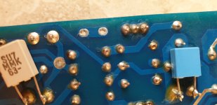
I can't check it now, but if I'm not mistaken, it was the empty hole seen in your picture I drilled out and put the HBR resistor to link the solder side layer with the top layer.
It has been some time since that, and I have moved on from these amps and worked on a lot of other amps since that
It has been some time since that, and I have moved on from these amps and worked on a lot of other amps since that
- Home
- Amplifiers
- Solid State
- L12-2 CFP Output amp 120W*2 8R