...does the L12-2 have no DC blocking caps on board?.......
The kit does have a small 10uF electrolytic at the input. Sounds quite nice with it . As I said earlier, you can hear the LF improve slightly without it. We are not comparing chalk and cheese !
")
It IS safer with a capacitor unless you walk the fine line like I do !
I once blew my Juli@ sound card while I was experimenting with a tube preamp . Accidentally touched the wrong side of the output cap. ! Sound card went bang when the smd cap blew up ! Haven't fixed it yet. Unable to get the SMD opamp it requires. It's the smallest version of the JRC4580. One channel works fine !
Purchased to finished boards with heatsinks
Version 2 I received today has 33mf electrolyt 25v cap in series as dc blocker but rest of board seems identical to latest versions mentioned .
Not over confident that heatsinks are heavyweight enough for my purposes ? loud in a large room but will add approx double the weight to the slimlineheatsink received.
I intend to for once have a loudspeaker protection kit installed but was curious about a heatsink cutoff switch.Any suggestions would be appreciated.
Yet to fire it up but will start with it in its supplied form and then try to do the upgrades/mods in two seperate goes later. The oversized Silmic may mean a number of Vishay resistors going onto reverse side.
I noted the suggestion that 649/669 s could be heatsinked and have assumed that this must be a sepeate heatsink per trannie.
I was also considering star heatsinks for the general 5401/5551 or devices or is that overkill?.
Looking forward to getting going.
Dave
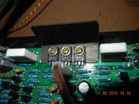
I put a small aluminum heatsink ( painted black) on the 649/669 and bias tr. Originally they appeared to just sit together on one long strip of pcb tinned track. With the current heatsink of about 45mm x 32mm x 1mm , it gets slightly warm after a couple of hours at medium volume. Would probably get quite hot without additional heatsinking at high volume (?). My sink is bent into an L along the length (45mm). So the 20 mm strip is actually perpendicular to the board.
heatsink advice
Hi and thanks for that.
Have found a couple of metal girder type heatsinks removed from previous work that may do for starters. 34 long x 22 wide and 2 x 10mm upward x 2mm thickness . So these may go a long way to solving the problem. Two holes in centre pre drilled so Its an easy fix. (Also have two spare) Especially before assembly.
They are also painted black.
If it gets really hot I can later add additional metal to the side 10mm wall(s) but I am intending to use one of these for adding a copper screen for a physical dividing wall between the two amplifiers as they will be in close proximity.
Will post photo when I learn how.
Note, over my many years of experimenting and listening I have notices how heat and overheating with lots of devices causes sonic change and not always for the good. Just have never seen any other people mention it over the years.
It was often sonically more noticeable than component changes but then again suggesting that used to be considered laughable.
Or is that another can of worms?.
.....suggesting that used to be considered laughable.
Or is that another can of worms?......
In 'audio' nothing is laughable until one has tried it for 'oneself' and proved/disproved that to himself ! It doesn't matter how it works out for someone else ! For 'you' only 'your own perception' matters ! The 'truth' is 'your perception only' !
Progress a bit slow but Ive fitted two heatsinks and machined up the additional output heatsinking as well as swapping 26 Vishays onto the boards.
Remainder and caps next time I m fit enough to update.
So far have made a start on casework. and fitted power supply with 2 x 52v (No load) DC .
20k caps per rail plus 100nf.
I note from previous postings that their may be an element of uncertainty about this type of circuit ?ie You must use protection ./?
This is probably safe advice but is it safe to fire up these boards without any output load ? ie 8 resistor .I am awaiting the two protection circuits.
Two early comments on the board from a previous builder.
It would have been nice to have a spare ground lug on the board for the other neg speaker lead.(My laziness?) Theres just about room next to the thiers 100mf electrolyt cap.?
I do miss the sight of two bright LEDs going on which always gave me confidence the white noise board was probably working fine.\thought I believe all leds cause noise to a circuit.
It was not a problem for me on the White noise amp.
Thanks for all so far.
I am hoping to go for a 500VA trafo when Im happy with the performance,.
Solid state amplifiers don't need a load to operate safely. In fact, never connect a load or input until the amplifier has been tested with a current limited power supply (e.g. bulb tester) fitted first and if the output's DC offset is acceptable, then proceed with bias current setting and use. Basic info. for safe testing of amplifier operation is available in many threads here and on many other audio sites.....You must use protection ./?
This is probably safe advice but is it safe to fire up these boards without any output load ? ie 8 resistor ......
safe testing advice.
Hi again and thanks for timely reminder.
Currently job is in very slow progress mode due to poor health issues including root canal work which hopefully resolves itself approx 6pm Tuesday.
Speaker protection boards now arrived and will now be fitted before the light bulb test (Already wired up).
Photos of project to be posted asap.
quick progress report Firdt impressions
Up and running with only minor hiccups as I had swapped out 40 plus resistors but no caps yet.Just impatient to get going and wow..So was it worth it.
Yes even at twice the price.
It also seems to have more power than I expected with a very tight grip over the speakers.
Initial reaction from a guy who has had,reviewed and repaired too may amps over the last 50 years ? It is Musically excellent from the off with almost no sonic signature and is running quite cool.
Not even sure I will swap out much more as it will sound better after initial run in.
Even better still its running a pair of small speakers and the biguns are yet to be treated to the new electronics..(see my Volt speaker thread)
If anyone is considering this kit then do not hesitate.
.
A very happy member. Up date to follow.
Just one question re the flexibility of the resistor values 68R ? can they be increased/decreased?.
Up and running with only minor hiccups
as I had swapped out 40 plus resistors but no caps yet.Just impatient to get going and wow..So was it worth it.Yes even at twice the price.
It also seems to have more power than I expected with a very tight grip over the speakers.
Initial reaction from a guy who has had,reviewed and repaired too may amps over the last 50 years ? It is Musically excellent from the off with almost no sonic signature and is running quite cool.
Not even sure I will swap out much more as it will sound better after initial run in.
Even better still its running a pair of small speakers and the biguns are yet to be treated to the new electronics..(see my Volt speaker thread)
If anyone is considering this kit then do not hesitate.
.
A very happy member. Up date to follow.
Just one question re the flexibility of the resistor values 68R ? can they be increased/decreased?.
.....just one question re the flexibility of the resistor values 68R ? can they be increased/decreased?.
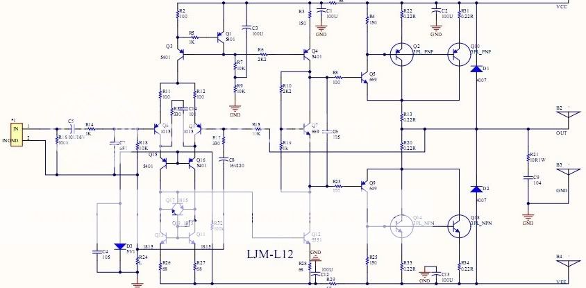
Referring to the L12 schematic (see discussion around #12), R26, 27 & 28 are the 68R resistors. Though changing resistor brands and types will only be cosmetic, changing values of the current mirror emitter degeneration resistors will affect the input stage and overall phase/stability margin. Changing R28 will affect the bias current of the VAS and have an effect on the thermal compensation and possibly the voltage amplifier's clipping behaviour.
Unless you have a technical reason for tinkering with something that ain't broke yet, don't alter these beyond 10%, since they are not arbitrary values. I would not call any advanced CFP design "flexible" enough to allow changing these components arbitrarily anyway.
Last edited:
No real technical reason
Thanks Ian for clarification.
I had left these set as unchanged from supplied resistors but had noticed from previous observations that some others (100R had been changed from 150R possibly an error?) So was just curious.
I did not have vishays in that value.
Meanwhile forgot to mention that DC blocking cap 1 has been removed and replaced at the phono inputs with a 3.9 high quality Mundorf cap bypassed with 10 nano f Vishay.
These has been boxed in with copper shielding and I have redesigned my whole units layout for the umpteenth time.
Taking a rest for the time being from the project.
Thanks again.
Finally up and running after doing the suggested extra solder on the track towards the output spades. A couple of extra vishays and the 681 caps replaced and that is it for now,note the New 500va traffo has yet to arrive.
Also had to change the power supply bridge to a solid 35 amp silicon which sonically is a step forwards and a step backwards?
Having read the power supply threads on this site to death I am more confused than ever.
Previously I had just 4 x 100n snubber caps on the schottky bridge (now removed) though I was never convinced this was correct.
Also I had half prepared a copper shielded enclosure for the bridge as well as using a well known rfi absorbing cloth wraopped around in order to reduce any adverse effect of diode switching.
I am now totally without any 100nf filter caps on the power supply feed and do not know which way to go ? as previous comments state the snubbers need a resistor to work properly ? I had previously been talked out of this by a designer.?
However the conventional practice has been 100n accross ac output of traffo and ? also 100nf accross ac ( poss and neg ) on traffo output each to ground (without a resistor.)
I had previously decided to bypass each of the 4 x 10000 caps with 100nf .
These are installed.
I presume that the sonic hardening ? difference I am hearing is because of the power supply changes to silicon diodes ? , rather than the small changes to the kit amp.note,Ive always preferred schottky diodes sonically.
You cannot fault the level of detail on this amp.
Sadly another two weeks break away from the project starts this weekend.
Subjective assessments made after considerable time lapses don't amount to useful data. You only have your impressions of sound quality that may have a grain of truth or none at all and this will lead to confusion and constant tinkering over time, as you chase elusive rainbows that only exist in your (fading) memory.
I am convinced that we become conditioned to sound qualities that may be a long way from ideal and subject to change as listener fatigue, moods, health etc. take effect. This means that improvements we hear may not be related to measured performance - that could actually be much worse and often is when we attempt to amend designs with only listening as a reference.
However, technically based power supply improvements make good sense regardless, provided you have a good design background and understand how snubbers work best. Otherwise, if like me you need professional help, have a look at the discussion and details of Mark's power supply design here: http://www.diyaudio.com/forums/vend...-pcbs-assembled-tested-units.html#post4366692
Three channels of my 4ch L12-2 build decided to self-destruct after I connected new cables with high(ish) capacity (the TNT Sonus Flatter cable, a 32 strand ribbon cable with alternating +-+-, 5uF for one run).
I installed the lightbulb limiter and checked the one remaining channel which seemed to be just fine with the cable and even played music on high volume with the typical "disco light" from the lightbulb. I can only assume the other channels went in the "Weee, I'm oscilating!" mode but can't be sure. The Marantz receiver I use now doesn't mind the cables (checked with a borrowed oscilloscope)
As I'd like to continue using the L12-2 I could use some suggestions how to proceed when the new modules arrive.
Yes, series output inductor should provide immunity against such exotic cables, but even then I do not think that such cables are necessary or even desirable. It's a pity to have expensive cables and not use them, but what marko is using is probably too radical provocation for many amps stability.
Hi,
I can drive my big Electrostats with those amps without any issues at all.
They present a much more complex load to the amps than a cable or most other speakers.
Makes me wonder a bit if the cables are the real source of desaster here.
A output RL network should help keep the amps on track though.
jauu
Calvin
Well, the cable could be called exotic, while it costs only a few dosen dollars it is a crucial part of my HiFi now. It is a DIY cable as described on the Italian site TNT audio, the cable is actually just a multi wire ribbon cable - the same type found in old ATA hard drives or wherever you need to transfer multiple signals to or from a PCB. It is crucial because it hides under the carpet - don't forget the Wife (girlfriend) Acceptance Factor - it is a neccessery compromise. I have a door bethween the speakers and it just doesn't work any other way.
Could you suggest values for the RL network? I've seen somewhere "wind n turns of fi diameter wire around a R ohm 3w resistor". I forgot the original values but they may need to be optimized anyway.
What about digging in to the schematic, maybe a compromise can be found by changing values or adding some components? I'll borrow the scope again when I get the new modules and start assembling them so the changes could be done incrementally until I get the modules stable.
Sent from my C6903 using Tapatalk
- Home
- Amplifiers
- Solid State
- L12-2 CFP Output amp 120W*2 8R