Member
Joined 2009
Paid Member
I was reading some comments from Pavel (who had designed an amp with a Lender VAS like my current TGM4 project) about the EF type 1 having lower high order harmonics compared with EF type 2 output [http://www.diyaudio.com/forums/solid-state/155628-solid-solid-state-power-amplifier.html#post1993755 ] when I remember reading an interesting article about an EF type output that had this very property.
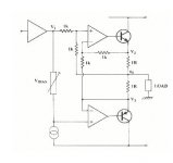
The link that explains what I'm referring to is here: Audio Amplifier Circuit Design
I've attached a diagram from that website to illustrate the simplicity of it.
An old thread here: http://www.diyaudio.com/forums/solid-state/30819-new-renardson-amp.html didn't reach any conclusions
I'm thinking of using this approach - any thoughts ???
Attachments
Last edited:
If I remember correctly, I had found at the time that I disagreed with Renardson's explanations on how his circuit works, but one fact is certain: it actually works. Which is the most important after all.
Hi Elvee, can you give details of how you think the Renardson's circuits works ?
Well, that was some time ago, and my recollections are a bit shady; in fact, I just remember I differed, but the details are completely lostHi Elvee, can you give details of how you think the Renardson's circuits works ?

I'll have to think about it, this should come back.
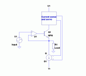
OK, here is my analysis.
I don't think it is the same I did initially, but one advantage when you have the memory power of a shrimp is that you have to permanently recreate and reinvent everything.
The top part of the circuit is basically a bridge, forced into balance by the opamp.
Of course, we suppose this is possible: the elements remain in their linear range, and the feedback has the correct polarity: negative.
By simple inspection, you can write that the balance condition is:
(V1+Vo)/2=(V2+V3)/2
Additionally, you can also write that Vo=(V2+V3)/2 - Io*1R/2
(Io is the output current)
Combining the two yields: V1+Vo=2Vo+Io*1R
Thus, Vo=V1-Io*1R
In plain English, this means the output voltage is equal to the input, minus the drop caused by the emitter resistors.
The important thing is that V2 and V3 have disappeared from the picture: the circuit manages V3 so that the output voltage is a scaled (and distortionless) version of the input.
This shows the circuit works, but it doesn't do so by magic: it is simply a local feedback loop around the top transistor, and talking about "error correction" or similar would be misleading.
It is an application of negative feedback, and the operation is governed by feedback theory; in particular, the performance of the circuit relies on the top amplifier having a high open-loop gain, and the circuit must satisfy closed loop stability criteria to work properly.
This is not to say that the circuit is not clever or worthless, quite the contrary, but it is important to understand it is a sub-class of unity gain followers.
The cleverness of the circuit lies in making sure the top transistor is always in charge, by keeping it active during what would normally be its idle period in a classic class B output.
This way, the output impedance remains finite, but constant and linear, and there is no hiatus at the crossover.
You could achieve an equivalent result by using the following alternative arrangement:
For positive signals, the buffer works normally, and during negative signals, the current servo imposes a constant minimum bias into the transistor.
Some buffers work that way.
But this is not forward error correction, it is simply a contorted way of applying feedback, and there are inherent and well-known limitations to that.
A true forward error correcting circuit is the crossquad.
Two further examples are the Tringlotron and Unigabuf
Attachments
Member
Joined 2009
Paid Member
is there a way to gain some benefit by exploiting the double EF output wherein the driver devices behave like small 'op amps' with their emitters as -ve feedback points. How would you structure such an 'improved' EF output ?
Schematic?
Member
Joined 2009
Paid Member
- Status
- This old topic is closed. If you want to reopen this topic, contact a moderator using the "Report Post" button.
- Home
- Amplifiers
- Solid State
- Anyone tried the Renardson Output Stage ?