Triple pure Darlington will have 3xVBE drop which is a clear drawback.
Quite so but easily overcome in a few ways.. my favorite being to use a regulated frontend voltage
Sziklai vs Darlington
Hi all
I'm a beginner in electronics so please forgive my errors.
Is thermal stability of the biasing current of the outuput transitors (related to 2 Vbe of driver transistors in CFP vs 4 Vbe of Darlington pairs) a reason for more stability with Sziklai configurations?
I've done a simulation comparison without heating effects. It looks like Darlington configuration behaves better. Am I right? Does a comparison like that have any meaning?
Cheers
The drawback is about thermal stability, hence quiescent current stability over room temperature and amplifier delivered power.
6 Vbe and large different power transistors.
Versus
2 Vbe of driver transistors in CFP.
Hi all
I'm a beginner in electronics so please forgive my errors.
Is thermal stability of the biasing current of the outuput transitors (related to 2 Vbe of driver transistors in CFP vs 4 Vbe of Darlington pairs) a reason for more stability with Sziklai configurations?
I've done a simulation comparison without heating effects. It looks like Darlington configuration behaves better. Am I right? Does a comparison like that have any meaning?
Cheers
Attachments
Your simulation isn't fine-grained enough, you'll get much better distortion figures if you fix that. If the simulation takes less than 10s to run, its likely not accurate enough.
You lack driver biasing resistors in both configurations. Your EF output stage lacks a speed-up cap. Have you optimized the bias current for each topology (normally 100mA for EF, 10mA for CFP is a good starting point).
CFP will be somewhat more linear, its got lots of internal negative feedback. This will be especially true driving low impedance loads like 4 ohms
CFP doesn't admit a speed-up cap so switching distortion is usually an issue at HF, especially with slow output devices like the 2N3055.
CFP can be harder to make stable due to the internal feedback, there are various tricks like adding small-value base resistors to output and/or driver transistors that can help.
Its not really a darlington strictly when the driver bias resistor and speed-up cap is in-place, its emitter-followers chained together. If you use darlington devices you cannot add the speed-up cap which is a strong reason to avoid them. The speed-up cap will reduce switching distortion a lot for the EF output stage, its major advantage (along with good stability).
CFP stage has somewhat less voltage overhead which is a major boon for 12V amplifier circuits, which are usually dual CFP amps in a bridged configuration to get the most from the 12V (and predrivers will be bootstrapped for the same reason).
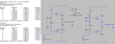
[ And here's my hacked version with various improvements (hopefully) and 4 ohm loads ]
You lack driver biasing resistors in both configurations. Your EF output stage lacks a speed-up cap. Have you optimized the bias current for each topology (normally 100mA for EF, 10mA for CFP is a good starting point).
CFP will be somewhat more linear, its got lots of internal negative feedback. This will be especially true driving low impedance loads like 4 ohms
CFP doesn't admit a speed-up cap so switching distortion is usually an issue at HF, especially with slow output devices like the 2N3055.
CFP can be harder to make stable due to the internal feedback, there are various tricks like adding small-value base resistors to output and/or driver transistors that can help.
Its not really a darlington strictly when the driver bias resistor and speed-up cap is in-place, its emitter-followers chained together. If you use darlington devices you cannot add the speed-up cap which is a strong reason to avoid them. The speed-up cap will reduce switching distortion a lot for the EF output stage, its major advantage (along with good stability).
CFP stage has somewhat less voltage overhead which is a major boon for 12V amplifier circuits, which are usually dual CFP amps in a bridged configuration to get the most from the 12V (and predrivers will be bootstrapped for the same reason).
[ And here's my hacked version with various improvements (hopefully) and 4 ohm loads ]
Attachments
Last edited:
Sziklai in output stage questions
Thanks for the advice.
How can I choose the right value for the speedup resistors?
Can I avoid the speedup capacitor using the Sziklai configuration?
I'm looking for a simple solution for my college simulation project (I'll do a proper thread about it asking for some other advices).
Your simulation isn't fine-grained enough, you'll get much better distortion figures if you fix that. If the simulation takes less than 10s to run, its likely not accurate enough.
You lack driver biasing resistors in both configurations. Your EF output stage lacks a speed-up cap. Have you optimized the bias current for each topology (normally 100mA for EF, 10mA for CFP is a good starting point).
CFP will be somewhat more linear, its got lots of internal negative feedback. This will be especially true driving low impedance loads like 4 ohms
CFP doesn't admit a speed-up cap so switching distortion is usually an issue at HF, especially with slow output devices like the 2N3055.
CFP can be harder to make stable due to the internal feedback, there are various tricks like adding small-value base resistors to output and/or driver transistors that can help.
Its not really a darlington strictly when the driver bias resistor and speed-up cap is in-place, its emitter-followers chained together. If you use darlington devices you cannot add the speed-up cap which is a strong reason to avoid them. The speed-up cap will reduce switching distortion a lot for the EF output stage, its major advantage (along with good stability).
CFP stage has somewhat less voltage overhead which is a major boon for 12V amplifier circuits, which are usually dual CFP amps in a bridged configuration to get the most from the 12V (and predrivers will be bootstrapped for the same reason).
Thanks for the advice.
How can I choose the right value for the speedup resistors?
Can I avoid the speedup capacitor using the Sziklai configuration?
I'm looking for a simple solution for my college simulation project (I'll do a proper thread about it asking for some other advices).
Simulate and tune for minimum distortion at 50kHz? Nearly everything in circuit design is a trade-off, and some things are hard to calculate (such as dynamic switching distortion) and need modelling or measuring ideally. There is no "right value", unless you carefully describe exactly what you are trying to maximize: "minimum distortion without too much quiscent current" isn't uniquely quantifiable.How can I choose the right value for the speedup resistors?
You can't have one, there's no place in the topology to actively pull current out of the output transistor bases...Can I avoid the speedup capacitor using the Sziklai configuration?
Cross coupling is an essential feature in any modern amplifier but it causes PSRR issues in a CFP output. Cross coupling extends the bandwidth and stability of the amplifier and prevents fatal high frequency shoot through current. It is so important that designers understand that power transistors need to be driven OFF as well as ON. You are driving the Miller capacitance, not so much the DC component. A small (~10 Ohm) base resistor is an alternative but it is not as good as an active negative/ off current source.
As others have pointed out, an accurate stable AB bias is difficult using a CFP. If you deliberately bias the output as high as 0.5A then the AB crossover is not an issue but the stability of that bias will require large emitter resistors and loss of efficiency, both at idle and when driven. Note that D Self warned against too much bias creating a zone of low-Z output that creates 3rd order distortion.
As others have pointed out, an accurate stable AB bias is difficult using a CFP. If you deliberately bias the output as high as 0.5A then the AB crossover is not an issue but the stability of that bias will require large emitter resistors and loss of efficiency, both at idle and when driven. Note that D Self warned against too much bias creating a zone of low-Z output that creates 3rd order distortion.
You can't have one, there's no place in the topology to actively pull current out of the output transistor bases...
Well, there is no good way. A capacitor between output bases does work as a "speed-up" aka cross-coupler, but it causes those outputs to react to any Power supply noise, although theoretically they cancel each other. Depending on the power supply, it may be a good idea used in moderation, ie less than 100nF.
In general, CFP is a good idea in low voltage amps where reducing output saturation voltage becomes more important than bandwidth and stability, but partial bootstrap drivers can make EF nearly as good while maintaining the high frequency stability. In either case, low output saturation requires care attention to rail sticking.
Last edited:
Why sziklai the best output audio stages .
Hello guys, I have concluded from several test that the sziklai pair output stage is better than the Darlington output stage just because if we assume to be the signal which is to cross two base emitter junction for darlington and one for sziklai, which of the two signals can make it to the output first. So in terms of Sonics quality the sziklai wins and also the low quiescent current of the sziklai makes it the best known audio output stage✌. But don't forget the 100pf capacitor between base and collector terminal of the negative rail driver transistor so fully stop parasitic oscillation.✋
Hello guys, I have concluded from several test that the sziklai pair output stage is better than the Darlington output stage just because if we assume to be the signal which is to cross two base emitter junction for darlington and one for sziklai, which of the two signals can make it to the output first. So in terms of Sonics quality the sziklai wins and also the low quiescent current of the sziklai makes it the best known audio output stage✌. But don't forget the 100pf capacitor between base and collector terminal of the negative rail driver transistor so fully stop parasitic oscillation.✋
Yes, in general this is the case.Hello guys, I have concluded from several test that the sziklai pair output stage is better than the Darlington output stage just because if we assume to be the signal which is to cross two base emitter junction for darlington and one for sziklai, which of the two signals can make it to the output first. So in terms of Sonics quality the sziklai wins and also the low quiescent current of the sziklai makes it the best known audio output stage✌. But don't forget the 100pf capacitor between base and collector terminal of the negative rail driver transistor so fully stop parasitic oscillation.✋
However go and test one at >=20kHz full swing and see their Achille's heel, switching distortion... There's no real way to add a speed-up cap to the CFP topology so the switch-off glitch is really difficult to tame, and it can even lead to heavy cross-conduction with ultrasonic frequencies.
At 1kHz or so the CFP reigns supreme, perhaps as low as 0.01% THD without global feedback is attainable (large swings, light loads), but as frequency and amplitude increases the performance will drop rapidly from some point due to this switching distortion. High frequency transistors are basically mandatory for a CFP stage, whereas EF is much more tolerant of sluggish devices. If you can keep switching distortion at bay till above 20kHz you have a great design.
In practice switching distortion depends on slew-rate, so lower signal levels tend not to have any issues from this, which is the majority of real signals fortunately,
but hardcore tests like 18/19kHz IM tests at full swing will tend to reveal it.
In short CFP OS topology is not very wide bandwidth, you'd not use it for driving an ultrasound transducer for instance.
Member
Joined 2009
Paid Member
- Status
- This old topic is closed. If you want to reopen this topic, contact a moderator using the "Report Post" button.
- Home
- Amplifiers
- Solid State
- Darlington or Sziklai (compound) pair output stages?