is important to know that the differential stage introduces emphasis
the correct method to apply the subtraction is the potentiometer
so it takes an inverting amplifier
preferably with high input impedance
is also good solution
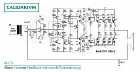
take the feedback current
able to equalize the performance of the speaker")
this is my configuration happier
provides a dynamic scene (XLR source indispensable)
detailed and intensive
the correct method to apply the subtraction is the potentiometer
so it takes an inverting amplifier
preferably with high input impedance
is also good solution
take the feedback current
able to equalize the performance of the speaker
this is my configuration happier
provides a dynamic scene (XLR source indispensable)
detailed and intensive
Attachments
Last edited:
This senses the output current. It will therefore raise the output impedance, which will create an 'interesting' frequency response with almost all speakers (which are usually designed for a low output impedance). For example, you will get a bass boost at the bass resonance. It may sound like a cheap ghetto blaster.
detailed and intensive
Have you actually built an M-9 clone?
Do you think the input fet buffer will actually work into a dead short?
Last edited:
Not a matter of filtering or crossovers, but driver and cabinet design. What controls the resonances, electrical or mechanical damping?stee said:my loudspeakers are unfiltered
I don't know what happens with cross-over
actually there is a problem with the resonance
the system oscillates in the radio frequency
when the gain control is very close to returning from shunt
I have 4 pieces of M9 with Motorola power Bjt
but I wanted to edit an A100
the model that was born before
http://www.diygene.com/schemas/a-100sch.pdf
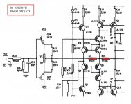
I deleted two input resistances and OP-Amp
to bring the next sequence M9
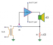
The PSU is made with 4X12V batteries with relais
and 2 switching PSU 24V
I have never heard better
a connection has been lucky
probably because it's rare to have an inverting amplifier
the system oscillates in the radio frequency
when the gain control is very close to returning from shunt
I have 4 pieces of M9 with Motorola power Bjt
but I wanted to edit an A100
the model that was born before
http://www.diygene.com/schemas/a-100sch.pdf
I deleted two input resistances and OP-Amp
to bring the next sequence M9
The PSU is made with 4X12V batteries with relais
and 2 switching PSU 24V
I have never heard better
a connection has been lucky
probably because it's rare to have an inverting amplifier
I have never heard better
I don't doubt this for a sec. Still, can you say into what impedance is the input buffer working? What kind of distortion can you expect from it alone?
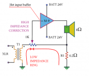
high impedance jfet input buffer
The input buffer is the heart of the system
because it allows you to bring out the detail with great accuracy
extrapolated from a difference (the potentiometer) from very low impedance
so as to avoid a tube preamp
to test the limit of the resonance
I applied a resistance 10khom
the potentiometer output
Tomorrow I will try to apply a small capacitor
As is normally used for the feedback resistor
and I will try to lower the shunt resistance of non-inductive 0R22
the transformer is the ideal tool to perform addition (Hot and Cold)
as said before
the differential stage (for the valves too) is not suitable for audio
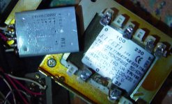
the best input transformer is a Tamura
600 to 300 ohm 2:1
This feature allows you to get a low susceptibility
of the source (DAC1 Little_Dot)
and also helps reduce the harmonics of even order
making the sound pleasant to listen to long
Bias is AB1 with a small fan on the radiator
not known at the time distortion
even with a full piano
still can not reach a minimum volume
The input buffer is the heart of the system
because it allows you to bring out the detail with great accuracy
extrapolated from a difference (the potentiometer) from very low impedance
so as to avoid a tube preamp
to test the limit of the resonance
I applied a resistance 10khom
the potentiometer output
Tomorrow I will try to apply a small capacitor
As is normally used for the feedback resistor
and I will try to lower the shunt resistance of non-inductive 0R22
the transformer is the ideal tool to perform addition (Hot and Cold)
as said before
the differential stage (for the valves too) is not suitable for audio
the best input transformer is a Tamura
600 to 300 ohm 2:1
This feature allows you to get a low susceptibility
of the source (DAC1 Little_Dot)
and also helps reduce the harmonics of even order
making the sound pleasant to listen to long
Bias is AB1 with a small fan on the radiator
not known at the time distortion
even with a full piano
still can not reach a minimum volume
Attachments
Last edited:
The input buffer is the heart of the system
I see you avoid my simple question. May be a language issue, so let's get some numbers.
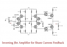
Originally, the fet buffer is loaded with a 470R resistor. At 1v input 1kHz second harmonic is around -80db and third -76db. Quite acceptable.
In your improved circuit fets are working into something closer to 30ohm load. Third harmonic is now at -41db.
Intensive indeed.
property of global feedback
because if you put the buffer in the feedback loop
After you have a low input impedance
that's why you need a transformer
Note that with the JFET into the ring
corrects the error of the buffer itself
to calculate the load buffer
must consider the current flowing on the common base input stage
because if you put the buffer in the feedback loop
After you have a low input impedance
that's why you need a transformer
Note that with the JFET into the ring
corrects the error of the buffer itself
to calculate the load buffer
must consider the current flowing on the common base input stage
Attachments
Last edited:
I have seen ccts. using chips which introduce shunt FB. What I would call a transconductance amp. The author never really felt it was an absolute solution more of an interest to be investigated.is important to know that the differential stage introduces emphasis
the correct method to apply the subtraction is the potentiometer
so it takes an inverting amplifier
preferably with high input impedance
is also good solution
take the feedback current
able to equalize the performance of the speaker
this is my configuration happier
provides a dynamic scene (XLR source indispensable)
detailed and intensive
In the schematic show there are far too many active and passive parts. Every part buggers the music!
Every part buggers the music!
It depends. The circuit above will generate more than 1% thd, mostly third and not counting the transformer. Apparently this contributes to an "intensive" sound.
What about simple version?
It depends. The circuit above will generate more than 1% thd, mostly third and not counting the transformer. Apparently this contributes to an "intensive" sound.
- Status
- This old topic is closed. If you want to reopen this topic, contact a moderator using the "Report Post" button.
- Home
- Amplifiers
- Solid State
- Shunt Current Feedback