Attached is a .doc which contains a .jpeg of a new amp design I've been working on. As of right now all I have is simulation, no test prototype. I was hoping some of the more knowledgeable engineers out there could check it out and help me optimize some values. Please no criticism based on subjectivism, this won't help. The amp topology is based on the Lin 3 stage with an EF type 2 output stage. The input is bootstrapped to lower the impedence of the NFB Network (lower noise). The input differential transistors are paralleled for the same reason. The VAS is a standard darlington with active load current source and buffers.
The output stage is EF type 2 utilizing a switchoff cap. As I said, any good engineering insight would be appreciated.
Thank-You,
The output stage is EF type 2 utilizing a switchoff cap. As I said, any good engineering insight would be appreciated.
Thank-You,
Attachments

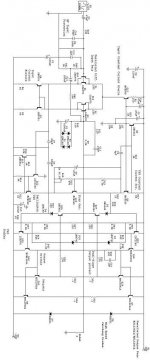
sss said:bad pic , many wires - no connection points !
There is no connection point, but this is not bad picture. If You check it carefully, You can understand it.
Sajti
I don’t see the utility of paralleling the input devices, the noise can only improve slightly if you use the 100 Ohm emitter degeneration R, in any event the better approach to paralleling would be to put equal value resistors (200 Ohm if you don’t want to change input gm) in all 4 Q emitters to assure current sharing without extra device matching effort
Andy_c’s sims in:
http://www.diyaudio.com/forums/showthread.php?postid=221474#post221474
and my reply further down suggest the mje350 Q9,13 are going to make lousy current sources without cascoding or other help
C6 is very interesting, looks like positive feedback to me, could be very twitchy, in general positive feedback increases gain variations in circuits – I would try to add “genuine”, linearizing gain to the VAS (and current source) with cascoding and/or the Baxendall “Super Pair” I discuss in the “Subjective Effects…” thread
I do like the 2nd order compensation but would definitely try Cherry’s trick of moving the connection to enclose at least Q29,30 if doesn’t work around the output devices (pre driver Q29,30 and diver Q12,18 bias current seem a little lite to me too, but I haven’t designed power output stages in a long while)
JCX, changes you would implement?
JCX, I have seen some of your postings and you seem very knowledgleable. I am trying to visualize your suggestions.
1. Forget the parallel input differential, the amount of noise will be negligible.
2. Emitter resistors of all four Q's (2 input, 2 current mirrors?) should be set to 100 ohms?
3. Miller compensation should include the pre-drivers (they are already included in the Global FB?) Are you talking about a separate nested feedback loop for only the pre-drivers? If so I would like to see a drawing or schematic on how to implement this. Also, I have heard that a lot of Cherry's ideas look good in theory, but are hard to implement. Have you found this to be true?
4. Yes, C6 is a small amount of positive feedback to cancel the feedthrough capacitance of the VAS current source in an attempt to create symmetric slew rate.
I earnestly await your reply,
Sincerely,
Brannon
On a second look at the circuit, I see two obvious problems: First the input resistor will compromise the noise so drastically that you don't need to parallel input devices, unless you use lousy ones. Second, the current source load degeneration resistors have to be increased well above 200 ohms, in order to reduce this contribution to the overall input noise. Hope this helps.
Mr. Curl,
Thank-you very much for your reply, it is much appreciated.
Through further investigation, I've found that the noise reduction afforded by the parallel input stage will have a negligible effect and I have decided to only use a single pair.
So if my calculations are correct, current through the current source load resistors and the degeneration resistors on the current mirrors will be balanced if R=100ohms.
Think it through. You must use greater than 100 ohms in your current sources in order to reduce the noise gain of the current sources. You will lose 3dB noise from the input stage at least. Is it really worth it? This is grad school level design, but it is correct. Anyone want to do a Spice emulation?
- Status
- This old topic is closed. If you want to reopen this topic, contact a moderator using the "Report Post" button.
- Home
- Amplifiers
- Solid State
- New Lin 3 stage design anyone?