Lineup's " JFET input, MOSFET VAS, LATERAL output = Perfect!! "
makes me think why not try to build a hybrid amp using tube VAS?")
(I know we should talk solid state here.)
I've already designed and diy a JFET+ JFET VAS+MOSFET 150W last year,
I always want to try a tube or a hybrid amp, but I am not good at tube designing not even mention to diy.
I don't know how to choose the tube and how much current should be set.
Is anyone interested in this topic?
Here is my circuit and I don't know how to use SPICE to simulate it.
makes me think why not try to build a hybrid amp using tube VAS?
(I know we should talk solid state here.)
I've already designed and diy a JFET+ JFET VAS+MOSFET 150W last year,
I always want to try a tube or a hybrid amp, but I am not good at tube designing not even mention to diy.
I don't know how to choose the tube and how much current should be set.
Is anyone interested in this topic?
Here is my circuit and I don't know how to use SPICE to simulate it.
Attachments
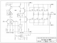
There is still a little problem in the first schematic I found just now, that the tube needs warm up time and during this time the output voltage is uncertain
just the same as my EU-152's when in standby mode.
So I need a at least 3min. start-up relay to protect the speaker, unlike solid state just needs few second. And I found that the DC servo can not be connected at MOSFET output directlly.
Sorry, it's my mistake.
just the same as my EU-152's when in standby mode.
So I need a at least 3min. start-up relay to protect the speaker, unlike solid state just needs few second. And I found that the DC servo can not be connected at MOSFET output directlly.
Sorry, it's my mistake.
Triodes in common-cathode mode have relatively high a-g capacitance, therefore I'm not too sure this would return any better results than a single fet or bipolar vas, and I'm reasonably sure it would be inferior to a cascode stage in terms of slew rate.
If you want to try this I would suggest driving the cathode from the drain of a fet, with the grid grounded. In other words a hybrid cascode. This will both eliminate the need for the questionable ac-coupled cathode bias arrangement, and give you the low miller capacitance advantage of a cascode.
Though personally I doubt if the inconvenience of warmup time, risk of DC offset damaging speakers, etc is justified.
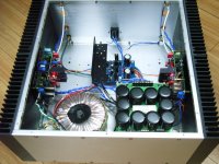
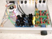
Nice job with the mosfet amp, mind you. Wish my wiring were as neat.
If you want to try this I would suggest driving the cathode from the drain of a fet, with the grid grounded. In other words a hybrid cascode. This will both eliminate the need for the questionable ac-coupled cathode bias arrangement, and give you the low miller capacitance advantage of a cascode.
Though personally I doubt if the inconvenience of warmup time, risk of DC offset damaging speakers, etc is justified.
Nice job with the mosfet amp, mind you. Wish my wiring were as neat.
Last edited:
If you were to parallel a MOSFET with a high positive gate voltage, it might allow
this VAS to run cold. And hopefully bias itself off after the triode warms. You might
need a driver of some sort for grid current, as the triode's grid will become leaky as
plate voltage drops... You need an LED under that Cathode, so that grid leak won't
distort the voltage seen below the cathode.
Triode models are at Duncan Amps, you probably need at least dmtriodep.inc
Index of /spice/valves
Last edited:
Member
Joined 2009
Paid Member
I like it - I think hybrids are a great area for play, new ground to explore. They don't take minutes to warm up - my tube amp is warm after a few seconds - too slow for a hybrid but not at all onerous for a start up relay delay on the amplifier output.
Am I reading your schematic right - looks like gnf and a dc-servo in parallel ?
I'm not sure what the concern is of a-g capacitance ? For the 6N1P it's listed at 1.6pF and you don't have gobs of gain in a tube to exert Miller multiplication in the same fashion that you have with a bipolar transistor.
And this is the weakness perhaps as the lower gain of the tube means lower OLG and therefore more distortion than with the use of a SS VAS. The real benefit of a tube, IMHO for VAS is the fact it is so linear it can be used without gnf. In a global nfb amplifier any tubes inside that loop are going to have their 'sound' ironed out of the equation.
But theory ain't worth much compared with a listening test. Can you get a tube in a socket and just hard wire it into your amp for a quickie test ?
Hi,
Tube VAS seems not the ideal place to use a Tube IMNSHO. Unless you use a Pentode gain will be very low (e.g. 6DJ8 will give you around 30dB Gain). It may work for a zero feedback Amp. There are quite a few example discussed here.
All of the extant hybrids that use conventional Op-Amp circuitry with tubes I know (for example the Sheng Ya Amp's from China) use the tubes in the input differential, where they arguably make most sense...
This said, Vladimir Shushurin did build an amplifier like that. The Middle stage was a 6DJ8 Mu Follower IIRC.
I think you may want to read up some on tubes. They are a lot like J-Fets, they are very similar to pentodes. While not really accurate, you may think of a triode as a J-Fet with a local feedback loop preceded by a J-Fet buffer.
Ciao T
Lineup's " JFET input, MOSFET VAS, LATERAL output = Perfect!! "
makes me think why not try to build a hybrid amp using tube VAS?
Tube VAS seems not the ideal place to use a Tube IMNSHO. Unless you use a Pentode gain will be very low (e.g. 6DJ8 will give you around 30dB Gain). It may work for a zero feedback Amp. There are quite a few example discussed here.
All of the extant hybrids that use conventional Op-Amp circuitry with tubes I know (for example the Sheng Ya Amp's from China) use the tubes in the input differential, where they arguably make most sense...
This said, Vladimir Shushurin did build an amplifier like that. The Middle stage was a 6DJ8 Mu Follower IIRC.
I think you may want to read up some on tubes. They are a lot like J-Fets, they are very similar to pentodes. While not really accurate, you may think of a triode as a J-Fet with a local feedback loop preceded by a J-Fet buffer.
Ciao T
where did you buy the amp modules ?
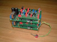
I made the two PCBs several years ago in order to try differnt kinds of audioamp's combination,
like preamp,headphone amp,and solid state power amps using MOSFET or BJT.
Attachments
Hi,
Really?
6DJ8 has 1.4pf Cag, do we have any sensible Vas transistors with < 1.4pF Cob?
If we use a pentode, we essentially get the equivalent of a Cascode in one bottle...
Folded Cascode.
In this case I think the tube is wasted...
Put the tube into the input and use a folded cascode with SS devices, that is much more of a "tube-amp" then, as the Tube dominated the current in the VAS Output Node...
With a 6DJ8 at 5mA per section at around 90V (certainly normal higher power amp territorry) gives 7mA/V transconductance, 60V/5mA gives around 6.5mA/V.
Folded cascode from this and a decently degenenerated current mirror would give the 7mA/V into the Vas output node, with (for example) 100K effective load we get around 57dB Open Loop Gain in first order approximation.
With a bit of luck, we may even get decent warmup behaviour...
Ciao T
Triodes in common-cathode mode have relatively high a-g capacitance,
Really?
6DJ8 has 1.4pf Cag, do we have any sensible Vas transistors with < 1.4pF Cob?
If we use a pentode, we essentially get the equivalent of a Cascode in one bottle...
If you want to try this I would suggest driving the cathode from the drain of a fet, with the grid grounded. In other words a hybrid cascode.
Folded Cascode.
In this case I think the tube is wasted...
Put the tube into the input and use a folded cascode with SS devices, that is much more of a "tube-amp" then, as the Tube dominated the current in the VAS Output Node...
With a 6DJ8 at 5mA per section at around 90V (certainly normal higher power amp territorry) gives 7mA/V transconductance, 60V/5mA gives around 6.5mA/V.
Folded cascode from this and a decently degenenerated current mirror would give the 7mA/V into the Vas output node, with (for example) 100K effective load we get around 57dB Open Loop Gain in first order approximation.
With a bit of luck, we may even get decent warmup behaviour...
Ciao T
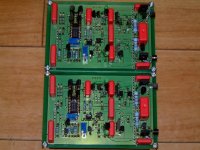
I made the two PCBs several years ago in order to try differnt kinds of audioamp's combination,
like preamp,headphone amp,and solid state power amps using MOSFET or BJT.
Interesting that you designed the pcb trails exactly as I think they should be: as "islands" with a thin "river" of free space between them.
Did you do it with a CNC or with common pcb design techniques?
Interesting that you designed the pcb trails exactly as I think they should be: as "islands" with a thin "river" of free space between them.
Did you do it with a CNC or with common pcb design techniques?
Believe it or not, I didn't know how to use professional pcb tools to generate Gerber file for the PCB manufacturers,
and I only had the simplest tool __ windows' paintbrush at that time (2003).
Using white line as the "river" cutting the black sheet to several "islands"
made the 3 films (holes, frontside and backside without parts print screen), and
thanks God that local PCB maker accept them, of course at minimum quantity
order 500 pcs each.
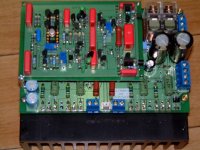
Though not expensive 500 pcs each were still beyond my need, so I sold some
bare PCBs for other diyers to make pre- and headphone amp.
One of my customer's preamp picture :
Attachments
Last edited:
- Status
- This old topic is closed. If you want to reopen this topic, contact a moderator using the "Report Post" button.
- Home
- Amplifiers
- Solid State
- How about a JFET input, TUBE VAS+buffer, and MOSFET output?