Hi All,
I'm rebuilding a crosspoint switcher for use with guitar pedals and thought this group would have some great insight. The problem is annoying hiss in the output signal of a box that was originally designed for production and studio work in the late '80s. I've re-purposed the unit to switch guitar effects.
Consequently, I'm changing the input from unbalanced low impedance (39K) to unbalanced high impedance (1M).
The power supply = 78xx/79xx regulators. I recently upgraded these with more modern replacements. Hiss is significantly reduced but still there. Would a "finesse regulator" solution help here to further quiet things down?
The audio section consists of a 5532 running as an inverting amp with a gain of .25 and an input Z of 39K. From the 5532, the signal goes to a CMOS analog switch to the output amps (5532 running as inverting amps with a gain of 4 and an output resistor of 47 ohms).
To use with guitar pickups and instrument level signals (100-300 mV), I set the input amps for unity gain with a 1M input and fdbk resistors. For the output amps, what value resistors should I use to set the gain? Should I use low resistance to keep the noise down (10K versus 100K)?
The output amp drives a 1K ohm load resistor instead of the original 47 ohm resistor. Should I go back to a lower value resistor than 1K?
The input Z of guitar pedals varies from 500K to 1M and their output Z can be from 100 ohms to 5K.
Thanks for bearing with the long post - it's my first. I haven't done any design work in decades so I would greatly appreciate any help.
Hi and Welcome to diyAudio ") I'm going to check with the other mods as to whether soild state is the best place for this thread. perhaps the instruments and amps section ...
I'm going to check with the other mods as to whether soild state is the best place for this thread. perhaps the instruments and amps section ...
Someone else will no doubt chime in, but some of the values of resistors do seem high to me, general rule is to use as low a value as is practical to minimise noise. Also I'm not sure why you would have any resistors in a unity gain feedback setup??
Tony.
I'm going to check with the other mods as to whether soild state is the best place for this thread. perhaps the instruments and amps section ... Someone else will no doubt chime in, but some of the values of resistors do seem high to me, general rule is to use as low a value as is practical to minimise noise. Also I'm not sure why you would have any resistors in a unity gain feedback setup??
Tony.
Thanks for the input, Wintermute. The main reason I put it in this section is that the issue I am battling is mainly about solid state noise from op amps and power sources - not so much the way in which I am using the gear. I'm happy with wherever you deem best to put this post.
The resistors for unity gain on the input is to raise the input Z beyond the 300K that the spec sheet says is the input resistance for a 5532. I need to get it up to 500k or more in order to not load down the guitar pickups. Loading the pickups changes the tone of the guitar - not a desirable effect in this case.
For the output op amps, if they don't need any resistors at all, that is even better. I bascially just followed convention of the original ckt. which had a negative gain resistor network on the input op amp and positive gain network on the output op amp for an overall unity gain. Your point is well taken, why do I need resistors on the output op amp section if I want unity gain?
A side not to all this is that the input op amps have a supply of +/- 5v DC. However, the output op amps have a supply of +/- 18v DC. My guess is that this has more to do with staying within signal specs for the CMOS switch that sits between the input and output op amps. It's max. VCC is +/- 10v DC, and it is powered off of the +/- 5v DC.
Again, any insights on how to reduce the hiss on this is welcomed.
Again, any insights on how to reduce the hiss on this is welcomed.
Thanks for the input, Wintermute. The main reason I put it in this section is that the issue I am battling is mainly about solid state noise from op amps and power sources - not so much the way in which I am using the gear. I'm happy with wherever you deem best to put this post.
The resistors for unity gain on the input is to raise the input Z beyond the 300K that the spec sheet says is the input resistance for a 5532. I need to get it up to 500k or more in order to not load down the guitar pickups. Loading the pickups changes the tone of the guitar - not a desirable effect in this case.
For the output op amps, if they don't need any resistors at all, that is even better. I bascially just followed convention of the original ckt. which had a negative gain resistor network on the input op amp and positive gain network on the output op amp for an overall unity gain. Your point is well taken, why do I need resistors on the output op amp section if I want unity gain?
I think this should probably be in the live sound/instruments forum - there are plenty of guys there who are working with solid state gear.
One thing I would say is that an inverting configuration at these high input impedances is a great recipe for noise particularly with a bi-polar op-amp, the problem is current noise, and probably voltage noise as well. A non-inverting design with a 1M input impedance and unity gain - a good fet op-amp could possibly be a better choice, lots to choose from, but the AD8510/8512 might be a good starting point, but if noise is a real issue even in a non-inverting configuration the LM4562 offers much higher loop gain than the 5532 and hence the possibility of much higher input Z.
For quietest operation you want to place the gain in the earliest stages possible while allowing for potential clipping issues - so gain before the first gain control should be limited to a value that will not cause output clipping with the highest anticipated input signal level.
I would jettison the CMOS switches, especially something like CD4051 etc. Much quieter alternatives from ADI, If you can source the current relays have virtually no noise. LM317/337 with 10uF on the adjust pin to ground knock down noise at the expense of transient response.
What could I replace the CMOS switch with? It is a CD74HC22106E. A replacement must be pin compatible or I would have to redesign the entire board - not an option.
Again, this is a dated design that uses dated parts. The 5532s, I can upgrade with lower noise pin compatible op amps - so long as the new op amps can handle the +/- 18v DC.
I replaced all of the old electrolytics caps and even the decoupling caps in the power supply. This made a huge difference, which is why I'm wondering if I can further lower the supply noise with a finesse regulator set-up. That is an after-market mod that I can add to the existing supply.
To the comment made about putting most of the gain in the early stages, I agree. It seems to me that a better design would have used 18v DC on the input op amps and the 5v DC on the output op amps, or 18v DC throughout to keep the signal well-above the noise floor.
Kevinkr - thanks for the suggestion about the LM4562. From the specs, that is one smokin' hot op amp - pin compatible, too. The 5532s I have are Philips. One thing that concerns me, can I get away with an 18v DC source on the 4562? The spec for the 4562 says that the VCC max is 17v. I'm not sure how hard the "max" limit is.
Also, not to ask a stupid question, but how do I interpret the input resistance spec on the data sheet? The Philips 5532 has an "input resistance" of 300K ohms. The "differential input Z" of the 4562 is 30K while the "common mode" input Z is 1000 M ohms. Which is most relevant to my situation? I want a high input Z so that I don't load the input signal.
Thanks to all for the education.
Bump.
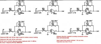
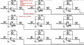
I've attached schematics are for the input and output sections of the unit. Both are very straight fwd., but my electronics knowledge is a little rusty. The only thing between the two amp sections is the analog switch that routes the inputs to the selected outputs.
The changes I've made are in red. Would I benefit from rewiring the DC supply to the input amp section to use +/-18 VDC instead of the existing +/-5 VDC?
Attachments
None of them.The Philips 5532 has an "input resistance" of 300K ohms. The "differential input Z" of the 4562 is 30K while the "common mode" input Z is 1000 M ohms. Which is most relevant to my situation?
Lets look at a couple of examples, assuming the input Z values you gave for the 4562 and assuming the opamp has a voltage gain of 10000 i.e. 80dB (at some or other frequency):
First circuit:
Ignoring R1, the input impedance at the input to the opamp itself is 30K in parallel with (R2/gain). Since R2/gain is about 100 Ohms, the 30K doesn't make much difference, the impedance there is about 100 Ohms.
The final input impedance of the whole circuit is R1 in series with that i.e. 1Meg + 100 Ohms. So even the 100 Ohms doesn't matter, input impedance is determined by R1 to several decimal places.
Second circuit:
The input impedance ignoring R1 = (differential input Z * gain) in parallel with common mode input Z = (30K * 10000) in parallel with 1000Meg = 300Meg in parallel with 1000Meg = at least 230Meg, probably closer to 300Meg, depending on phase. So again, the final input impedance is defined by R1 as 1Meg. The 230Meg (or whatever) makes little difference.
Third circuit:
The input impedance ignoring R1 = (differential input Z * gain/11) in parallel with common mode input Z = (30K * 10000 /11) in parallel with 1000Meg = 27Meg in parallel with 1000Meg = at least 26.5Meg. So again, the final input impedance is defined quite accurately by R1 as 1Meg.
Bottom line - you seldom, if ever, need to worry about the input impedance if opamps.
Cheers - Godfrey
Attachments
Unity gain is good, High resistance (1 Meg) raises the noise.To use with guitar pickups and instrument level signals (100-300 mV), I set the input amps for unity gain with a 1M input and fdbk resistors.
10k is better. Right now, most of the noise is from the input stage, so you need to fix that first.For the output amps, what value resistors should I use to set the gain? Should I use low resistance to keep the noise down (10K versus 100K)?
Doesn't make much difference.The output amp drives a 1K ohm load resistor instead of the original 47 ohm resistor. Should I go back to a lower value resistor than 1K?
Doesn't matter, see my previous postThe resistors for unity gain on the input is to raise the input Z beyond the 300K that the spec sheet says is the input resistance for a 5532.
The input Z of guitar pedals varies from 500K to 1M and their output Z can be from 100 ohms to 5K.
Does the signal always go from guitar to effects pedal to switcher, or does it also (sometimes) go direct from guitar to switcher? The guitar only cares about the input impedance of the thing it's plugged into.I need to get it up to 500k or more in order to not load down the guitar pickups. Loading the pickups changes the tone of the guitar - not a desirable effect in this case.
If all the inputs to the switcher are from effects boxes, a low input impedance (e.g. 10k) is fine. You only need high impedance (e.g. 1Meg) if the guitar is plugged directly into the switcher.
Godrey,
Thanks for taking the time to respond so completely. The guitar plugs straight into the switcher.
As an experiment, I changed the gain and input Z via the op amp's input and fdbk resistors on different inputs and listened to each individually to determine the affect on tone. The higher the input Z, the closer to the original guitar tone (plugging straight in to the amp) I got - as I would expect. Tone went from lifeless and slightly dark to dynamic and sparkly.
Resistor values used were 39K (unchanged), 100K, 500K, 1M. Gains I used were .25 (unchanged), 2 or 1. With gains of .25 and 2, I had an equal and opposite change in gain on the output amps to get to unity gain for the switcher.
The result was that unity gain using 1M resistors sounded the most accurate. I also noticed that changing the input Z had an effect on hiss - that was part of the criteria I used to determine what sounded best. Oddly, with 1M, the hiss was slightly less noticeable - opposite of what I would expect.
I agree, the noise is from the input side, which is why I'm also attacking supply noise and will experiment with different op amps, too.
switching guitar pickups before preamp/buffering is not easy, can't be done with low noise and your amp topology - even the length/type of cable between inductive pickups and their preamps can change "the sound" since small C, high R change resonant frequency, damping in the audio frequency range
put preamp/buffers in front between the Guitar pickups and anything else including the crosspoint
then the original crosspoint circuit vaules can be OK
put preamp/buffers in front between the Guitar pickups and anything else including the crosspoint
then the original crosspoint circuit vaules can be OK
That is effectively what I am doing except that the buffer/preamp happens to be in the crosspoint unit itself, right?
The white noise I am trying to get rid of is present as soon as I connect the switcher output to the amp, regardless of whether there is anything connected to the input or not. It was there before I made any changes to the op amps. The most significant change to the noise level was the result of power supply changes. A more subtle change occurred when I made the op amp Z/gain changes.
My kingdom for a lab-grade power source to experiment with.
That's surprising. I wouldn't have expected the power supply to introduce significant noise.The most significant change to the noise level was the result of power supply changes. A more subtle change occurred when I made the op amp Z/gain changes.
As far as the opamp circuit is concerned, if you want low noise with high input impedance, then a non-inverting configuration is needed. The unity gain buffer shown previously should be ideal. Unfortunately, I expect you'd need to hack the circuit board a bit to do that. Maybe you could do one as an "air sculpture" to try it out without damaging the PCB.
- Status
- This old topic is closed. If you want to reopen this topic, contact a moderator using the "Report Post" button.
- Home
- Amplifiers
- Solid State
- Noise Reduction Solutions