Hi,
Input stage is similar with bjt in "current feedback" topology - meaning that feedback is connected to emiter/source instead of base/gate and we don't have anymore LTP's. The main difference is that feedback is connected this way into a low-impedance node.
Taking this into account I'm not sure that we can connect an op-amp instead of T1&T2 if we want to keep "current feedback" idea.
Regarding use of current mirrors - I remember that I saw somewehere a schematic, I will have a search for it and I will post it if found. The idea was to "unload" the input stage from the VAS perspective and to have a bigger load impedance for the input stage. Please correct me if I'm wrong.
regards,
Tibi
hi fojica, you may read posts #14 and #15 in http://www.diyaudio.com/forums/solid-state/164476-kuroda-tl071-60w-fet-amp-1982-a-2.html
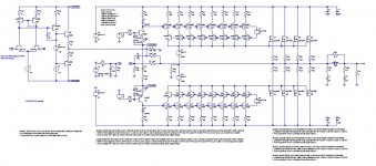
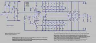
Both versions (MOSFET output / BJT output) give the same 0,0007% THD 1KHz 60Vpp 4 ohm.
Both versions (MOSFET output / BJT output) give the same 0,0007% THD 1KHz 60Vpp 4 ohm.
Attachments
Last edited:
Hello kenpeter, the Feral1 schematic qualifies for so many things ! Full symmetry, non-slewing ultrafast input stage (reminds me Stochino), current mirror load, Schottky-based servo soft non-switching class AB bias, electrolytic capacitors management.
However, due to the absence of intermediate VAS stage, I wouldn't say that Feral1 is truly member of the Full Symmetry 1973 Motorola, 1976 Leach, 1978 Borberly-Hafler lineage.
Could the Full Symmetry 1973 Motorola, 1976 Leach, 1978 Borberly-Hafler lineage benefit from the Schottky-based servo soft non-switching class AB bias ? Have you tried on simulation ?
Feral1 may qualify as member of the 1983 Hiraga "Le Monstre" lineage. In such lineage we find J.M. Plantefève "Zenotron", Selectronic "ProFet", and Nelson Pass "F5".
Could the Hiraga "Le Monstre" lineage benefit from the Schottky-based servo soft non-switching class AB bias ? Have you tried on simulation ?
It would be more easy to categorize Feral1 into the Hiraga "Le Monstre" lineage if you manage to derive a version with FETs at the input. Imagine the consequences if the FET-input Fera1 is better than the BJT-input Fera1 on simulation ! See the Hiraga "Le Monstre" lineage here : http://www.diyaudio.com/forums/solid-state/194917-modern-incarnations-hiraga-le-monstre.html
Another way to look at Fera1 is to consider that it is a genetic fork basing on the Hiraga "Le Monstre" lineage, in quest of more gain and more speed in the input stage.
The definition of such new lineage would be : non slewing differential input (see Stochino), current mirror loads, no intermediate VAS, and MOSFETs output devices used in common source. There of course, due to the current mirror loads, you realize that you need the Schottky-based servo soft non-switching class AB bias. No need to say, in such lineage you can have a BJT input stage or a FET input stage.
Cheers,
Steph
Last edited:
Hello wahab, obviously it was the 1973 Motorola app note. Can you please research the 1977 version of the CC2 Audionics ? This is of importance because it may thus predate the 1978 Borberly-Hafler.1977 CC2 Audionics , whose schematic was taken from a manufacturer app note.(was it Fairchild.?) This the 1979 version.
In this case I have start this thread two years ago:I still don't know why Ben Duncan is referring to Lender. Is there a publication from Lender ?
http://www.diyaudio.com/forums/soli...age-large-voltage-swings-lenders-circuit.html
I ask my self the same question after looking to the references about
http://www.bgaudioclub.org/uploads/docs/High_Performance_Audio_Power_Amplifiers,_B.Duncan.pdf
check out also this:
http://www.diyaudio.com/forums/solid-state/99967-anybody-have-scan-483b-motorola.html
http://www.ing.unlp.edu.ar/catedras/E0215/list.php
Last edited:
a design idea for kenpeter
Looks like it could work.
But only if that op-amp is class A with a high quiescent.
No need to clarify "?" branches in the crayon drawing,
I understood exactly what you were suggesting.
Years of Smoking Amp's chicken scratchings upon coffee
stained napkins have prepared me to read anything.
-------------
I think your 12R bypass is located wrong side of the
base stoppers. Output current would run away as you
have drawn it... Else you will need a taller diode stack
with a wastefully increased voltage drop.
Last edited:
My mistake. Sorry. Sould be on the Schottky side. I'll put my glasses next time.I think your 12R bypass is located wrong side of the
base stoppers. Output current would run away as you have drawn it... Else you will need a taller diode stack with a wastefully increased voltage drop.
Rudolf Lender and Erno Borbely were working at Motorola. Rudolf Lender was a Field Application Engineer in Germany. Erno Borbely was working at the Central Application Lab in Geneva, Switzerland.
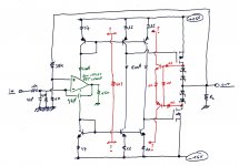
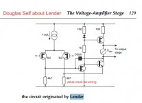
In his "Audio Power Amplifier Design Handbook", Douglas Self draws the Lender circuit incorrectly. See attached picture.
Clearly, anyway, such Lender circuit is unapplicable to True Symmetry amplifiers.
So why is Ben Duncan referring to Lender, it in his book "High Performance Audio Power Amplifiers" ? Answer : because the VAS degeneration resistor gets shared with one of the differential stage collector resistor, possibly saving one copper track on the PCB. But that's not the essence of the Lender circuit.
Let's temporary forget about True Symmetry amplifiers for concentrating on the Lender circuit. If you look again to the Douglas Self schema, you understand that the essence of the Lender circuit is to interpose a common collector buffer between the differential collectors and the VAS base, and save a few parts into the current mirror loading the VAS collector. The buffer operating current gets defined by the 1000 ohm resistor going to the positive supply rail. Such current is nearly constant, as we are before the VAS, no big voltage excursions. Note here that the 1000 ohm value is unrealistic if using high supply voltages like +42V and -42V. The current will be too big. Second Douglas Self mistake here. A value of 4700 ohm or 10000 ohm would be more appropriate. Anyway, as as consequence, the same current line can be used to define the master current of the current mirror loading the VAS collector. The degeneration resistance in the VAS emitter is not 4700 ohm, but 47 ohm or so. In order to possibly save one copper track, such resistor gets shared with one of the differential collectors. Now look : the obvious drawback of the "Lender simplification" is to introduce VAS quiescent current changes caused by supply voltage variations. Such "Lender simplification" should thus be avoided unless regulated supplies.
One could do a LTspiceIV simulation of a True Symmetry amplifier, a simple model with the differential input stages loaded by resistors. One version with the VAS emitter degeneration resistor going to the supply rails. Another version with the VAS emitter degeneration resistor shared with one of the collector loads. Then determine if there is a behaviour change.
Attachments
Last edited:
Both circuits basiclly the same than that one by post #3 abouthi fojica, you may read posts #14 and #15 in http://www.diyaudio.com/forums/solid-state/164476-kuroda-tl071-60w-fet-amp-1982-a-2.html
Both versions (MOSFET output / BJT output) give the same 0,0007% THD 1KHz 60Vpp 4 ohm.
http://www.diyaudio.com/forums/soli...wire-100-aw-100-aw100-different-versions.html
tiefbassuebertr, "basically the same" ? How so ? This time you are completely wrong. Try to understand what's a Kuroda.Both circuits basiclly the same than that one by post #3 about
http://www.diyaudio.com/forums/soli...wire-100-aw-100-aw100-different-versions.html
"basically the same" means, that feedback network is connected into a low-impedance node instead a high impedance node like by LTP usual.tiefbassuebertr, "basically the same" ? How so ? This time you are completely wrong. Try to understand what's a Kuroda.
Sorry, don't want to trigger a war, a Kuroda isn't arranged such way and doesn't work such way. Please read the Kuroda thread in full."basically the same" means, that feedback network is connected into a low-impedance node instead a high impedance node like by LTP usual.
- Status
- This old topic is closed. If you want to reopen this topic, contact a moderator using the "Report Post" button.
- Home
- Amplifiers
- Solid State
- Borbely-Lender True Symmetry