In the Bart Locanthi amp, there are two differential pairs in series, isn't ? I would say that such amp is the originator of the Hitachi amp (the one that went so popular with lateral MOSFETs). Not exactly the blameless filiation, thus.I think the first blameless was Bart Locanthi's amp from when he was working at JBL. It is also based on the Lin topology This would have been about 1968 (maybe JC can help out here). I took a look at his circuit and was amazed to find that all the things you need to do to create a TID free amp were in that design and, he also understood output stage distortion quite well too (inventor of the EF2 and EF3).
HI Steph
Yes, IMHO this Bailey sounded better than his 30W. The reference is:
"Wide band d.c. coupled power amplifier for laboratory service" which appeared in Electronic Engineering, December 1968, pp688-694.
It was basically a differential input version of his 30W but as it did not appear in Wireless World it did not get the coverage.
On AB testing it came out better, I think (I heard?). But subjectivity is not a topic for engineering other than to measure and explain it ...
John
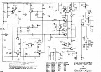
Bad news, I can't say that the Marantz Model 15 dating back from 1966 is a "blameless" ancestor. Okay, it has a differential input (long tailed pair Q102 Q103) fed by a current source (Q101) but that's all. Q104 Q105 Q106 are not the kind of VAS you'd expect from a "blameless". This beind said, the Marantz Model 15 schematic is far for being uninteresting, with the CFP arrangement at the output. Why CR112 and CR113 ? I would expect a low value resistor between CR112 anode and CR113 cathode. Has anyone tried replacing Q102 Q103 by matched FETs, Q109+Q110 (and Q112 +113) by a MOSFET, and using Schottky diodes for CR112 and CR113 ? This would deserve a dedicated DIYaudio thread.jez, thanks for having provided the Marantz Model 15 schematic. I'm taking the liberty to reproduce it here, from your post on DIYaudio http://www.diyaudio.com/forums/solid-state/194562-diodes-instead-across-emitter-resistors-2.html Very interesting post indeed. Will somebody organize a LTspiceIV simulation ?
Attachments
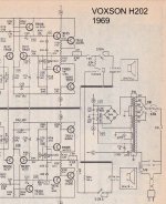
In 1969 there is the Voxson H202. The differential input pair isn't fed by a current source. The VAS gets loaded by a capacitive boostrap arrangement. This is actually worse than the Sinclair Z30/Z50. The Sinclair Z30/Z50 has the VAS loaded by a constant current source.
Attachments
Why CR112 and CR113 ? I would expect a low value resistor between CR112 anode and CR113 cathode. Has anyone tried replacing Q102 Q103 by matched FETs, Q109+Q110 (and Q112 +113) by a MOSFET, and using Schottky diodes for CR112 and CR113 ? This would deserve a dedicated DIYaudio thread.
I think Kenpeter gave valid explanations in some of his posts, diodes in the output being one of his pet subjects.
To summarize his views (which i agree with), the diodes "extend" the exponential characteristic of the B-E diode, but without the huge heating caused by the collector junction.
Removing the emitter degeneration resistors in a class B PP improves linearity, but it also is extremely risky.
Using external diodes mitigate the risk (not completely, apparently, since light bulbs have been added: there must still be some times when things go badly wrong).
The other purpose is to prevent shutdown of the inactive device: at high currents, the apparent resistance of the diode becomes very small, and the total voltage of the base spreader is still sufficient to keep both devices on.
This also gives a much softer transition, with crossover artifacts "diluted" over a large voltage range.
In my view for a amp to be blameless as in Selfs theories the following design criteria must be present, LTP current mirror, LTP degeneration, ccs at LTP and vas, miller compensation, beta enhanced vas and EF2 outputstage. As far as I can see none of the previous posts shows any design that intergrates all the criteria so shouldnt be regarded as blameless.
Ill try get some writings of JLH in electronic form dating from 1979, in these he fulfills all the blameless criteria.
Ill try get some writings of JLH in electronic form dating from 1979, in these he fulfills all the blameless criteria.
Agree with you, but you see, if we call those amps "pre-blameless" we'll get thousands of people coming with the H.C.Lin (RCA - 1956) "complementary and transformerless push-pull" topology. So, how would you call the Sonab R4000/U700 power amplifier dating back from 1969 ? Make a proposition (max 16 letters, space included).In my view for a amp to be blameless as in Selfs theories the following design criteria must be present, LTP current mirror, LTP degeneration, ccs at LTP and vas, miller compensation, beta enhanced vas and EF2 outputstage. As far as I can see none of the previous posts shows any design that intergrates all the criteria so shouldnt be regarded as blameless.
Attachments
Last edited:
Just a Lin topology with enhanced beta vas, its still missing the current mirror, its very close though, do you perhaps know who the designer was ??. I guess the nearest we can get is to find out who came up with the different schemes that make up a blameless for instance the current mirror or the beta enhanced vas, it would be interesting. What D Self did very well indeed was to combine all these features to make a amp with extraordinary performance while keeping complexity to a minimum. One has to use quite a lot more parts to be able to inprove on it.
Yes, D.Self Blameless amplifier incorporates all those features. I consider the "Blameless" methodology of using each of these features adjusted to get the best performance that the topology allows.
Any one can assemble an amplifier that includes all the components referred to in the earlier listing, but that alone does not make it "blameless".
The bias currents throughout the amp are critical to extracting "true blameless" performance. Then you have to add in the external factors eg, psu and cable routing.
Self even shows three different versions of his Blameless and goes on to tell us that some of the features he fitted can be replaced with alternatives. Using those suggested/recommended alternatives does not remove the "Blameless" from the amp building methodology.
Last edited:
Very interesting point. I guess all those "pre-blameless" amps suffer from assymetric dV/dt (slew-rate). Fast VAS turn-on happens with the long tailed pair current rushing into the base of the VAS, while slow VAS turn-off happens by the VAS base discharging into the collector resistance of one of the differential. This is not the case with a current mirror as load : VAS turn-off can be fast, with the mirror "actively" sinking the VAS base charges out.Just a Lin topology with enhanced beta vas, its still missing the current mirror, its very close though, do you perhaps know who the designer was ??. I guess the nearest we can get is to find out who came up with the different schemes that make up a blameless for instance the current mirror or the beta enhanced vas, it would be interesting.
Douglas Self doesn't say the same. He says "Putting a current-mirror in a well-balanced input stage increases the total O/L gain by at least 6 dB. Another happy consequence is that the slew rate is roughly doubled, as the input stage can now source and sink current into Cdom without wasting it in a collector load".
So yes indeed, I would like to know who "invented" the current mirror load in the differential input stage, and when. It could be somebody involved into IC design, just after the µA709 or so.
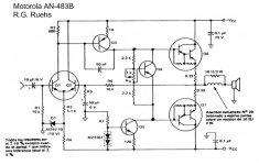
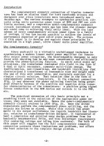
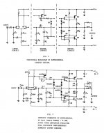
Clearly, within Motorola in 1967 (Haas AES publication), the current mirror as load for the differential stage had not been disclosed yet. See attached pictures.
Could it be that this particular AES publication from Haas in 1967, working at Motorola, is the milestone marking the end of the H.C.Lin era, and the beginning of the blameless era ?
If yes, I would agree to name all the "pre-blameless" amplifiers, "G.C.Haas" amplifiers.
Attachments
Last edited:
............the following design criteria must be present, LTP current mirror, LTP degeneration, ccs at LTP and vas, miller compensation, beta enhanced vas and EF2 outputstage.
you omitted the 8distortions, three of which (5 to 7 incl.) are outside the amplifier.Andrew like I said in the post 27,
Yes, D.Self Blameless amplifier incorporates all those features. I consider the "Blameless" methodology of using each of these features adjusted to get the best performance that the topology allows.
Any one can assemble an amplifier that includes all the components referred to in the earlier listing, but that alone does not make it "blameless".
The bias currents throughout the amp are critical to extracting "true blameless" performance. Then you have to add in the external factors eg, psu and cable routing.
Self even shows three different versions of his Blameless and goes on to tell us that some of the features he fitted can be replaced with alternatives. Using those suggested/recommended alternatives does not remove the "Blameless" from the amp building methodology.
Exactly!
There is no such topology as the "blameless" as such. More a set of techniques that can be applied to most topologies to optimise them in line with the methods pioneered by Self.
")
- Status
- This old topic is closed. If you want to reopen this topic, contact a moderator using the "Report Post" button.
- Home
- Amplifiers
- Solid State
- very first "blameless" amplifier prior 1969