...then again the 32 opamp power amp can apparently drive 8ohms to 16W (44mA per chip?).
jayam000 did say that he has a lot of NE5532s on hand...
I like "mad" circuits like these.

How will we discover new things if we do not stray from the beaten path? There are still a few true pioneers around, it seems.
Hello,
Without splitting curly red hair the circuit in post 1 will output in the range of 0.125 watts into 32 ohms or 200 ohms for that matter, ample enough to damage your hearing. Worth building!
My preference for the real buffer is the near 0 output impedance.
DT
All just for fun!
Without splitting curly red hair the circuit in post 1 will output in the range of 0.125 watts into 32 ohms or 200 ohms for that matter, ample enough to damage your hearing. Worth building!
My preference for the real buffer is the near 0 output impedance.
DT
All just for fun!
Here is the schematic for the current dumping headphone amp that was design by my late friend Barry Porter. The only problem is sourcing the choke L1 which only has the RS part No.238-255.
PCB layout.
I have used it with various headphones and it has worked well with Audio-Technica, Sennheiser & Beyerdynamic.
PCB layout.
I have used it with various headphones and it has worked well with Audio-Technica, Sennheiser & Beyerdynamic.
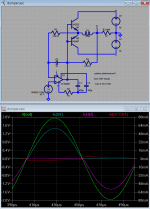
I've simmed "current dumping" to try to understand more of its capability, limitations
the power combiner is a AC Bridge that needs trimming to get good performance - you have to match L/R, RC time constants, compensate for L dcr - requires 'scope and distortion measurement - won't "just happen" with standard RS parts
http://www.diyaudio.com/forums/soli...r-requirements-class-c-ab2-4.html#post2388517 the sim still works - I have to ask LT about the missing output comp pin on LT1028
Class A buffer in the op amp feedback loop is much simpler to get to work, should give better results even when current dumping is optimally trimmed
Current dumping works quite a bit better if you don’t have the deadzone in the power amp – a little bias helps a lot
Attachments
Last edited:
- Status
- This old topic is closed. If you want to reopen this topic, contact a moderator using the "Report Post" button.