I read a letter to Electronics World magazine from Jim Bongiorno just the other day in which he claimed that crossover distortion in power amps had been cured many years ago by the use of diodes in place of the emitter resistors in the Marantz Model 15 power amp designed by Sid Smith and that he had later improved on this by using a combination of schottky diodes and resistors in a later design of his own....
In my many years of involvement in audio electronics I can't recall ever seeing this topology and a google search of the subject has come to nought!
I'm assuming that if there was really any mileage in this it would be commonplace by now!?
Anyone familiar with the idea and care to comment on it?
In my many years of involvement in audio electronics I can't recall ever seeing this topology and a google search of the subject has come to nought!
I'm assuming that if there was really any mileage in this it would be commonplace by now!?
Anyone familiar with the idea and care to comment on it?
This is not the first time that Bongiorno has claimed that crossover distortion was cured years ago. If it was that simple everyone would be doing it.
To eliminate crossover distortion you need the transconductance of the output stage to be roughly constant, irrespective of signal level. This means that at the quiescent point (where both sides are conducting) the gm of each side needs to be about half of the gm of one side at full signal (when only one side is conducting). It is difficult to see how this can be achieved if the gm changes with signal, as a diode would seem to imply.
Alternatively, you run at a high quiescent current and accept central gm-doubling and switching distortion at some other signal level. Some people prefer this.
Probably something like John Broskie's class AC.I read a letter to Electronics World magazine from Jim Bongiorno just the other day in which he claimed that crossover distortion in power amps had been cured many years ago by the use of diodes in place of the emitter resistors in the Marantz Model 15 power amp designed by Sid Smith and that he had later improved on this by using a combination of schottky diodes and resistors in a later design of his own....
In my many years of involvement in audio electronics I can't recall ever seeing this topology and a google search of the subject has come to nought!
I'm assuming that if there was really any mileage in this it would be commonplace by now!?
Anyone familiar with the idea and care to comment on it?
Make a search with these terms, it might answer your question.
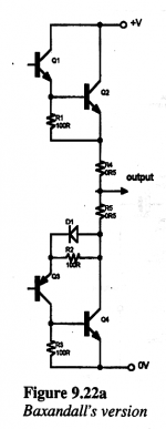
There could be other reasons: Baxandall diode fe.
Or something completely different: in the Circlophone©, resistors serve purely as current sensors, and have no effect on the transfer function.
They thus have a relatively large resistance, to maximize the sensivity, and they are shunted by schottky's at high current where they play no role, to avoid wasted power.
There might be other reasons....
My two pennorth: diodes are highly exponential just like transistor bases. Therefore, to remain even approximately linear, they need to be biased on, slightly, just the same as a transistor. If not, either they will cause a high non-linearity when they do (for the case where diodes are in parallel with the emitter resistor) or the output stage is not biased enough (in the case where only diodes are used) and the output stage will be operating in Class B as opposed to Class AB and have a high crossover distortion anyway.
Using diodes it seemed to me was a crude trick to try to control quiescent current at the expense of linearity.
Using diodes it seemed to me was a crude trick to try to control quiescent current at the expense of linearity.
Yes, exactly. To a first approximation the diode has the same response as the thing you are trying to correct. It is a bit like adding an extra BJT to a Darlington, except that this one has a beta of 1.
I don't do much SS now, but some years ago I had a look at p-p outputs (specifically the complementary pair). The biggest problem is thermal stability. Setting the quiescent current for low crossover is easy - you can even calculate the optimum value. The trick is keeping it correct as everything heats up.
I wrote it up for Wireless World about 10 years ago. Bongiorno wrote in and said that it was all unnecessary as the problem had been solved years earlier.
there are a few related techniques, it helps to know a few search terms to get started
try the forum Goolge Search button with
Tanaka, Pass;
square law output;
non switching output
http://www.diyaudio.com/forums/solid-state/162559-new-class-super-non-switching-need-revival.html
http://www.diyaudio.com/forums/soli...tortion-class-ab-output-stage-topologies.html
http://www.diyaudio.com/forums/soli...-biasing-non-switching-class-ab-overflow.html
I've seen something like that in a few guitar amps. Basically a diode in parallel with 1 - 5-ohm emitter resistor of one power transistor. But they have always had the typical low-ohm emitter resistor in there as well as well as the the ordinary vbe mult bias circuit + thermal compensation. So, I hardly see how the diode would have mysteriously solved anything.
If I rememeber correctly, the Marantz scheme was somewhat unique but basically not too different from the scheme of using diode voltage drop to bias the output devices. In Marantz the diodes (if I remember right) where just placed in another place instead of the usual between driver bases location. Effectively the biasing means with diode voltage drop varying with temperature was still the same - and just as bad as using only plain diodes for the task.
Key words are also: "many years ago". Things in solid-state design have come lightyears ahead from what they were many years ago, say, in 1960's. ;-)
Last edited:
Found this on the website of Bongiorno's current employer. It appears to say that the Marantz Model 15 was NOT fully complementary, but the amp JB worked on next (SAE-31B) WAS fully complementary.
So if the Marantz Model 15 was not fully complementary, perhaps it was Quasi complementary, and perhaps it benefited from the Baxandall diode.
So if the Marantz Model 15 was not fully complementary, perhaps it was Quasi complementary, and perhaps it benefited from the Baxandall diode.
Early in his career, James worked at Marantz. He was contributing engineer with the Sid Smith as senior engineer in the project for the Marantz Model 15 Power Amplifier which was the first example of a topology that is virtually identical to most modern power amps. Some high-end designs have moved past this topology to a fully complementary one, which as it turns out was developed by James in 1973 (Scientific Audio Engineering 31B). Slightly later a higher-power version called Ampzilla was introduced by James as a kit design in Popular Electronics. Demand for both the kit and assembled unit created such demands on James’s time that he was soon running is own company, GAS (The Great American Sound Co.), producing this 200-wpc unit and its baby brothers with cute names such as Son of Ampzilla (first separate power amp I ever owned -KWN). James also introduced preamps that incorporated the new balanced topology. Other innovations included the introduction of DC servo circuits (Theadra, 1975) and very low-noise phono preamps that did not need a pre-preamplifier stage.
Maybe I'm mistaken. I'm far from an audio expert, but has not elvee just accomplished this? from the thread:
...Here is something different for a change:
It combines a circlo output topology with an active bias servo.
The servo stabilizes the quiescent current, but it goes further: it actively controls the output stage so that both sides always remain active in a "warm" class AB, having most of the attributes of the full class A, including a complete absence of crossover artifacts.
Meet the Circlophone©!!!
For my surprise I've just simulated an amp adding in parallel the SCHOTTKY's B560C to each OP BJT Re (.22) and THD is better by a 7% at 10KHZ and 16% at 200KHZ, other conditions equal (560 ma AB bias) OLG profile not changed .... small signal OL distortion is the same for both cases, what intrigues me is the little but noticeable reduction of THD with the SCHOTTKY's when closing the loop ???
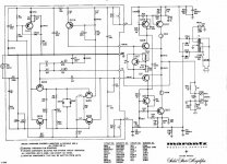
And here is the Marantz Model 15. Apart from the diodes, notice the bulbs in the emitters as well! And the DC coupled output was very advanced for the time. Not to mention the inductors in the emitters of the second stage diff amp many years ahead of the 990 discrete op amp...
Interesting design!")
Interesting design!
Attachments
Thanks for the circuit.
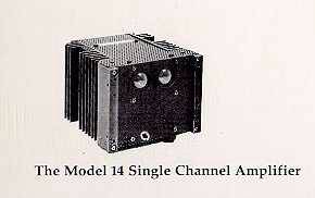
The amp looked like this:

The Model 15 is/was unique in other ways as well. It is two mono amps in seperate cabinets held together by the faceplate. There are even two power cords! Apparently those bulbs in the OPS are now getting hard to obtain.
The mono block was sold seperately as the Model 14.
The amp looked like this:
The Model 15 is/was unique in other ways as well. It is two mono amps in seperate cabinets held together by the faceplate. There are even two power cords! Apparently those bulbs in the OPS are now getting hard to obtain.
The mono block was sold seperately as the Model 14.
Last edited:
You mean the collectors? To what purpose?And here is the Marantz Model 15. Apart from the diodes, notice the bulbs in the emitters as well!
Thats just rediculously overcomplicated.
Much simpler ways to get the job done..
Attachments
Last edited:
Apparently the lamps lit up when the amp was in overdrive condition. I guess they are the little blobs on both sides of the Marantz name in the photo above, but I have never seen one.
When they blow, my hunch is that the amp stops working. If only one blows, would there be a DC offset on the output?
Owners report that VW Beetle tail light bulbs work well as replacements now that the originals are becoming unobtainable.
When they blow, my hunch is that the amp stops working. If only one blows, would there be a DC offset on the output?
Owners report that VW Beetle tail light bulbs work well as replacements now that the originals are becoming unobtainable.
Last edited:
- Status
- This old topic is closed. If you want to reopen this topic, contact a moderator using the "Report Post" button.
- Home
- Amplifiers
- Solid State
- Diodes instead of or across emitter resistors