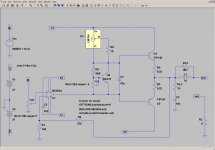
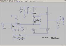
Here is my suggestion for an amplifier that is as simple as possible, but no more than that. The main design objective was to get a low-priced amplifier with as few components as possible, while still getting good performance.
To this end, I went for integrated circuits and Darlington transistors. I even went as far as using the LM334 current source. A conventional current source has at least five components, maybe more. The design might not be the last word in state of the art and high performance, but it is as simple (and cheap) as I can make it.
LTspice has this amp giving at 1kHz:
A 4 ohm load might be okay in a bridged configuration but each output transistor then has to source 7A of current. They have an absolute maximum rating of 10A, so we are sailing a little close to the wind here.
At these power levels, we might be able to do away with the Zobel network, or maybe just bits of it. Any thoughts on this would be appreciated.
There are various ways of getting more power out of this design, but then the cost and/or number of components goes up. The first way is to use a higher supply voltage and to drop the supply to the op-amp with Zener diodes. You then need an output stage with voltage gain. This can be achieved with complimentary feedback pairs and local feedback, However, all of the simplicity is gone.
Another way is use a high voltage opamp like the OPA551, which can handle a supply of + 40V. This will give about 70W of output power. However, these opamps are fairly expensive, which defeats the design objective. And for just a little more money you can use the LME49830 input stage from National Semiconductor.
Using an op-amp in a power amplifier seems to be a bit of a technological dead end, for the reasons mentioned above. But if you don't want a lot of power, it serves its purpose.
To this end, I went for integrated circuits and Darlington transistors. I even went as far as using the LM334 current source. A conventional current source has at least five components, maybe more. The design might not be the last word in state of the art and high performance, but it is as simple (and cheap) as I can make it.
LTspice has this amp giving at 1kHz:
- 16W into 4 ohms with a THD of 0.045%
- 32W into 8 ohms with a THD of 0.027%
A 4 ohm load might be okay in a bridged configuration but each output transistor then has to source 7A of current. They have an absolute maximum rating of 10A, so we are sailing a little close to the wind here.
At these power levels, we might be able to do away with the Zobel network, or maybe just bits of it. Any thoughts on this would be appreciated.
There are various ways of getting more power out of this design, but then the cost and/or number of components goes up. The first way is to use a higher supply voltage and to drop the supply to the op-amp with Zener diodes. You then need an output stage with voltage gain. This can be achieved with complimentary feedback pairs and local feedback, However, all of the simplicity is gone.
Another way is use a high voltage opamp like the OPA551, which can handle a supply of + 40V. This will give about 70W of output power. However, these opamps are fairly expensive, which defeats the design objective. And for just a little more money you can use the LME49830 input stage from National Semiconductor.
Using an op-amp in a power amplifier seems to be a bit of a technological dead end, for the reasons mentioned above. But if you don't want a lot of power, it serves its purpose.
Attachments
Member
Joined 2009
Paid Member
I'd keep the Zobel, it's not about power but about avoiding parasitic oscillations of the output pair and it prevents r.f. entering the amp via the negative feedback loop.
Don't you want a capacitor in series with R1 to ensure gain rolls off at dc (better dc-offset stability) ?
Don't you want a capacitor in series with R1 to ensure gain rolls off at dc (better dc-offset stability) ?
Member
Joined 2009
Paid Member
You could add a VAS which would reduce the drive voltage needed from the opamp.
not allowed - you have to reduce parts count not increase
")
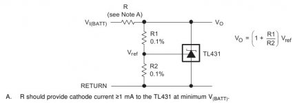
How about you ditch the constant current source with a resistor, replace the Vbe multiplier with a TL431 to maintain a constant voltage ?
Last edited:
not allowed - you have to reduce parts count not increase
How about you ditch the constant current source with a resistor, replace the Vbe multiplier with a to maintain a constant voltage ?
That's what I'm talking about - (nearly) ruthless simplification. It will reduce the parts count by one. The picture below (from the TL431 datasheet) shows how it is done. I will investigate further.
Attachments
I'd keep the Zobel, it's not about power but about avoiding parasitic oscillations of the output pair and it prevents r.f. entering the amp via the negative feedback loop.
Don't you want a capacitor in series with R1 to ensure gain rolls off at dc (better dc-offset stability) ?
That additional capacitor will really have justify its existence. When I get round to building one, I will check it out. LTspice does not provide answers on this. It is certainly needed in a discrete long tail pair with not-quite-matched transistors, but my thoughts at this stage is that the NE5534 will have the DC offset thing well under control.
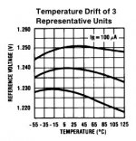
Replacing the Vbe multiplier with a TL431 or LT1009 might not be a good idea. There will be no thermal coupling to the output transistors, as these voltage references are designed to maintain a constant voltage no matter what the temperature (see graph from LT431 datasheet below).
In a simulation it does work. I ran it with the LT1009 model included in LTspice. What happens when things get hot is another question, though. It seems like a good idea that will not work. The comprehensive TL431 application notes from National Semiconductor does not mention this seemingly obvious idea. Perhaps there is a message there. Any thoughts?
In a simulation it does work. I ran it with the LT1009 model included in LTspice. What happens when things get hot is another question, though. It seems like a good idea that will not work. The comprehensive TL431 application notes from National Semiconductor does not mention this seemingly obvious idea. Perhaps there is a message there. Any thoughts?
Attachments
Last edited:
Once made tries with the 5534 as base for low power amps,
and did build some , using as well 5532s when factor form
is in the low size range.
In the simulators , assuming the model is accurate enough ,
it s amazing that ppm class THD is not out of reach , despite
the simplicity of the schematics.
and did build some , using as well 5532s when factor form
is in the low size range.
In the simulators , assuming the model is accurate enough ,
it s amazing that ppm class THD is not out of reach , despite
the simplicity of the schematics.
Member
Joined 2009
Paid Member
bootstrap is a good idea, more headroom to +ve rail for sure, maybe it's possible to bootstrap for the -ve rail too ?
yes, without Vbe multiplier thermal runaway is a problem, I'd overlooked that. I wonder what value of emitter resistors at the output would be needed to stabilize without Vbe (distortion could be higher) ?
yes, without Vbe multiplier thermal runaway is a problem, I'd overlooked that. I wonder what value of emitter resistors at the output would be needed to stabilize without Vbe (distortion could be higher) ?
Would a standard CE or CFP output stage give better performance? Lateral fets even?
A standard CE or CFP output stage will give better performance, especially in frequency response and ergo slew rate. The TIP142 and TIP147 does not seem to be the fastest trannies in the spares drawer.
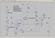
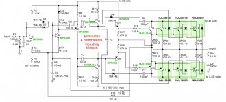
MOSFETS is a possibility. They don't need need emitter resistors like BJTs do. You don't even need a Vbe multiplier. Here is a variation on the theme, with a high-voltage op-amp. Not quite simplified yet and I haven't tried it at a lower supply voltage, but you get the idea.
I will ditch the Vbe multiplier and use the current source from the previous circuit and report back. The feedback around the op-amp can be left out at a small cost in phase margin as well.
Attachments
Last edited:
I wonder what value of emitter resistors at the output would be needed to stabilize without Vbe (distortion could be higher) ?
That's certainly worth a look.
Another option would be to use the Thermaltrak transistors from ON Semi. They have built-in diodes for thermal tracking.
Here is a full-house circuit for the Thermaltraks from an application note. Combined with a HV op-amp, the parts count might be just right. They will need drivers, but losing the Vbe multiplier with its need for adjustment would make it worthwhile. There seem to be a market/need for DIY amps that do not need any adjustment between build and use.
Attachments
I intend to realize such an amp for checking various older and currently available OP-Amps in the DIP-8 outline and the SO-8 outline.Here is my suggestion for an amplifier that is as simple as possible, but no more than that. The main design objective was to get a low-priced amplifier with as few components as possible, while still getting good performance.
To this end, I went for integrated circuits and Darlington transistors. I even went as far as using the LM334 current source. A conventional current source has at least five components, maybe more. The design might not be the last word in state of the art and high performance, but it is as simple (and cheap) as I can make it.
LTspice has this amp giving at 1kHz:
The limiting factor is the power supply voltage of the NE5534 op-amp, which is + 22V. If more power is required two of these can be bridged. The generously dimensioned Darlington output transistors will handle the additional current required, but only into an 8 ohm load.
- 16W into 4 ohms with a THD of 0.045%
- 32W into 8 ohms with a THD of 0.027%
A 4 ohm load might be okay in a bridged configuration but each output transistor then has to source 7A of current. They have an absolute maximum rating of 10A, so we are sailing a little close to the wind here.
At these power levels, we might be able to do away with the Zobel network, or maybe just bits of it. Any thoughts on this would be appreciated.
There are various ways of getting more power out of this design, but then the cost and/or number of components goes up. The first way is to use a higher supply voltage and to drop the supply to the op-amp with Zener diodes. You then need an output stage with voltage gain. This can be achieved with complimentary feedback pairs and local feedback, However, all of the simplicity is gone.
Another way is use a high voltage opamp like the OPA551, which can handle a supply of + 40V. This will give about 70W of output power. However, these opamps are fairly expensive, which defeats the design objective. And for just a little more money you can use the LME49830 input stage from National Semiconductor.
Using an op-amp in a power amplifier seems to be a bit of a technological dead end, for the reasons mentioned above. But if you don't want a lot of power, it serves its purpose.
An interesting fact is the reaction of the error of the output buffer, which is still present in the not "Class-A" mode (distortion with complex character through idle current only between 20 and 50 mA).
Because this buffer stage is inside of the NFB loop, the necessary standarts of the OP-AMP (e. g. GBP = product of gain and bandwidth) must be much more higher than by normal line stages (and even than by RIAA stages with high voltage gain factor).
Thus the differences in sonic character between the various OP-AMP types must be actually also much more larger (and from other kind) by use in such an amp topology than by use in usually line stages.
How is here the audible perception of the differences between various op amp IC's from Analog devices (AD797), Burr-Brown OPA627, OPA827) and National Semiconductor (LME series) ?? This would be very interesting to know.
The maximum achievable output power by +/-15V is enough for checking this.
I will replace the darlingtons with discrete components, because here I can use various values and topologies for the emitter resistors of the first darlington stages (driver transistors). This isn't possible by darlingtons, because this are actually integrated circuits with two transistors and two resistors.
BTW - where goes the current from the emitter of transistor U6 (VBE Multiplier transistor from attached schematic post #1) ?
And what is the advantage for use of the integrated CS unit instead two resistors from the voltage rails to C and to E from U6?
Last edited:
For more power out of an opamp frontend the QSC topology is better. They have schematics on their website.
Here is a simple one:
http://qscaudio.com/support/library/schems/Discontinued/Series One/1080.pdf
Here is a simple one:
http://qscaudio.com/support/library/schems/Discontinued/Series One/1080.pdf
For more power out of an opamp frontend the QSC topology is better. They have schematics on their website.
Here is a simple one:
http://qscaudio.com/support/library/schems/Discontinued/Series One/1080.pdf
Very interesting output stage topology! Am I right in assuming that the collectors of both output transisters are at ground potential and hence, they can be mounted directly on heatsinks without insulators? Any other adverse effects or points to be taken care of?
--gannaji
BTW - where goes the current from the emitter of transistor U6 (VBE Multiplier transistor from attached schematic post #1) ?
I got the original idea for the circuit from a sub-woofer amp circuit in the book "Build your own high-end audio equipment" published by Elektor. I wondered about the same thing myself, but it works. It seems that the op-amp sinks it. I confirmed this in LTspice, but can that be the right way of doing things.
Attachments
- Status
- This old topic is closed. If you want to reopen this topic, contact a moderator using the "Report Post" button.
- Home
- Amplifiers
- Solid State
- Very simple class B amplifier