Hi, I'm trying to design an audio mute with a remote switch. That is, a switch on a long line that can be run to any convenient position on stage. The muting unit itself will sit between the audio snake an a mic cable. Because of the application, a simple switch on the muting unit won't do. The switch must be located away from the unit. My thought had been to use a transistor as the switch in the muting unit...and apply power to the base of that transistor through the long remote cable. This way the audio signal wouldn't be routed through unshielded cable. But I can't wrap my head around how this might work. I can draw from phantom power in the snake, taken though resistors, so I have a power source to work with. But transistor switches require current from base to emitter, correct? Not just voltage present and the base. Soooo, Pin 2 | collector Pin 2--> resistor-\ | --> switch --> base --> | Pin 2--> resistor-/ | emitter | Won't work...right? Pin 3 Is there a way to connect pins 2 & 3 using a transistor. Such that closing a switch 10 feet away will activate the short (mute)? Any thoughts are much appreciated. Thanks
(let's try that again) Hi, I'm trying to design an audio mute with a remote switch. That is, a switch on a long line that can be run to any convenient position on stage. The muting unit itself will sit between the audio snake an a mic cable. Because of the application, a simple switch on the muting unit won't do. The switch must be located away from the unit. My thought had been to use a transistor as the switch (shorting pin 2 and 3) in the muting unit...and apply power to the base of that transistor through the long remote cable. This way the audio signal wouldn't be routed through unshielded cable. But I can't wrap my head around how this might work. I can draw from phantom power in the snake, taken though resistors, so I have a power source to work with. But transistor switches require current from base to emitter, correct? Not just voltage present and the base. Soooo, ...........................................................Pin 2 .............................................................| Pin 2--> resistor-\ .................................collector .........................> --> switch --> base --> | Pin 2--> resistor-/ ...............................emitter .............................................................| ...........................................................Pin 3 Won't work...right? Is there a way to connect pins 2 & 3 using a transistor. Such that closing a switch 10 feet away will activate the short (mute)? Any thoughts are much appreciated. Thanks
Well, if you are going to use a transistor, use a JFET, not a bipolar. JFETs are "on" until turned off by a voltage at the gate. SO connect source-drain across your balanced line. I leave it to you to scout out the details.
What are you muting? I want to guess a microphone, but could be anything. And since you want it remote, may I assume it is not for vocals? Otherwise the person singing or talking into it could easily flip a switch right at his/her mic. SO maybe someone can turn off say the acoustic guitar mic when not being played? Or kill some other mic in front of the drums? SOmething?
Since you have a snake, I have to assume you are not mixing from the stage, yes? SO that impplies a soundman back at the mixer. Then why can't he turn off that mic?
I am not suggesting your plan is wrong, I just want to wrap my head around the problem you are solving.
I'm sorry about the formatting...Something isn't working right.
I'm not dedicated to using a transistor, I just want to find a way to allow remote switching.
I'd prefer the normal state be an open circuit (not-muted). That way is something gos wrong, like the remote switch being disconnected, the audio will keep working.
I'm muting a lav mic on a pastor who tends to cough alot. So I'm looking to put a footswitch at near him to momentarily mute the lav. The way the cables are strung his wired lav cable trails away to the right, which is good because he doesn't trip over it that way. But a normal pro co cough drop (tm) would require his lav cable to plug in at his feet. Bad.
So I want to keep the cabling the same, trailing way from him, and add a muting unit near the snake, but with a thin line over to his feet for the switch. And I thought it best to avoid routing audio through unshielded cable.
Some lavs have a mute switch on the beltpack, ours doesn't. And on top of that, I've watched this pastor used such a switch...he doesn't remember to unmute it, and it just doesn't work well.
I do mix for the service, but I rarely catch his coughing fits in time.
I've got a handle (I think) on the pin2-3 bridge for the muting circuit, but I'm stymied as to how to trigger that electrical short remotely.
Thanks for your suggestion, I know very little about the different transistors available.
Does a transistor exists that is the opposite of the jfet? That is, off until triggered by a voltage at the gate?
Lastly, what happens to the voltage at the gate... does it affect the source-drain signal in any way? For the mute to work I need to connect pins 2 and 3 in both directions with little to no added noise.
Thanks again,
David
I found one more note to add to this discussion.
http://www.dutchforce.com/~eforum/index.php?showtopic=5201
This page shows a normally open transistor switch.
I have to admit I'm not solid on the theory here. It looks like voltage at the gate should lets current flow through source-drain. Any thoughts?
http://www.dutchforce.com/~eforum/index.php?showtopic=5201
This page shows a normally open transistor switch.
I have to admit I'm not solid on the theory here. It looks like voltage at the gate should lets current flow through source-drain. Any thoughts?
I've been drawing circuits and I think by having two jfets I can rig a normally open transistor switch.
So, Pins 2 and 3 each have a resistor attached to them, and those resistor outputs are joined to provide the + voltage line.
The + line is split into 2 branches, one branch goes to a remote switch, (plus an indicator led and it's paired resistor)
the line returning from the remote switch assembly is connected to jfet1 gate.
the other + branch is run into the source of jfet1.
Thus, if the remote switch is open (normal) current flows through jfet1 from source to drain.
When the remote switch is closed, voltage is applied to jfet1 gate, blocking source-drain current.
the output of jfet1 is fed to the gate of jfet2.
The source for jfet2 is pin 2 and the drain in pin 3.
Thus, when the remote switch is normally open, voltage is present at the gate of jfet2, and no current flows from source (pin2) to drain (pin3) of jfet 2.
So the mic would be on.
When the remote switch is closed, voltage is applied to jfet1 gate, stopping current flow from jfet1 source to drain.
When jfet1 stops outputting voltage to the gate of jfet2, jfet2 source-drain current flows, shorting pin2 and pin 3. muting the mic.
Whew....does that make any kind of sense?
The thread in this link talks about muting circuits
Microphone switcher assistance
Also, this google books result talks about it alittle.
Small Signal Audio Design - Google Books
One more link that hold a wealth of information (most of which is well over my head at the moment)
Selecting the Right CMOS Analog Switch - Maxim
And lastly, I think I found a possible answer:
this page notes, "The enhancement mode MOSFET is equivalent to a "Normally Open" switch.".
Metal Oxide Semiconductor MOSFET Tutorial
Last edited:
If this works, this is a rough schematic for a mosfet based mute.
I'm sure I'm missing some components, but I don't know enough to guess what those might be.
Any comments are very welcome.
An externally hosted image should be here but it was not working when we last tested it.
I'm sure I'm missing some components, but I don't know enough to guess what those might be.
Any comments are very welcome.
Last edited:
@nico:
I'm open to the idea of using a relay. That was, in fact, my first thought. But I was worried that a magnetic field so close to a mic level cable might introduce some issues. Secondly I worried that a relay would required more power than phantom power could provide.
If those are both non-issues, then I'm happy to use a relay.
My objective is simply a phantom powered noiseless muting circuit, with a remote switch. Any method that achieves this is fine with me.
@pinkmouse:
The muting cicuits I've seen generally use a capacitor and resistor to connect pins 2 and 3, with a normal unmuted condition. To mute, the resistor is bypassed leaving pis 2 and 3 connected by a capacitor. The tech sheets indicate this is a low pass? filter. The purpose is to ensure that the dc level is equal between pin 2 and pin 3...preventing pops.
Douglas Self shows a "series-shunt" transistor mute block that incorporate a few more items.
I'm sure I haven't learned enough to do this yet, but I hope I'm getting there.
Thanks
Last edited:
A single transistor works fine...
See page 25 of the Cirrus reference design for the CS42528:
http://www.cirrus.com/en/pubs/rdDatasheet/CRD42528-2.pdf
You can use FET's, but bipolars work just fine with standard CMOS logic levels.
See page 25 of the Cirrus reference design for the CS42528:
http://www.cirrus.com/en/pubs/rdDatasheet/CRD42528-2.pdf
You can use FET's, but bipolars work just fine with standard CMOS logic levels.
Hi Fixer,
I think that a relay mute/unmute is likely to give an audible click.
I further think that FET mute/unmute can be turned on/off sufficiently slowly to avoid that click.
It could probably be achieved in 100us to 1000us, rather than instantly.
A bit like a very fast resistor fade.
I think that a relay mute/unmute is likely to give an audible click.
I further think that FET mute/unmute can be turned on/off sufficiently slowly to avoid that click.
It could probably be achieved in 100us to 1000us, rather than instantly.
A bit like a very fast resistor fade.
@ neil: I may be reading that design wrong, but it looks like the transistor pulls the audio output to ground. I've seen many designs that do this, but I don't think that will work for me. My mute is based on connecting pin 2 and pin 3, not pulling them to ground. Which should, if it works properly, connect the + signal and the - signal, summing them, and producing a flat output. Meanwhile I have to keep those pins connected to the mic because they also provide power.
@andrew: thanks for the input. I had thought about a "slow mute" if for no other reason that it may sound better than having a sharp drop in system noise. We're talking in the millisecond range here, but it may be noticeable... I don't know. Of course, that adds yet another layer of complexity to this device. I'd have to bother with ramping up the power to a transistor in a controlled way.
@andrew: thanks for the input. I had thought about a "slow mute" if for no other reason that it may sound better than having a sharp drop in system noise. We're talking in the millisecond range here, but it may be noticeable... I don't know. Of course, that adds yet another layer of complexity to this device. I'd have to bother with ramping up the power to a transistor in a controlled way.
An externally hosted image should be here but it was not working when we last tested it.
Two mosfets in antiseries make an AC mosfet.
Well current doesn't flow through the gate. The gate capacitance charges up and this turns the FET on.
When both fets are on, the electricity can travel through the body diode of one mosfet which for some reason is not shown there.
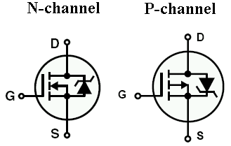
Since the fets are in antiseries, and the diodes are in antiparallel with the fets, AC can either flow or get blocked depending on the state of the fets.
When both fets are on, the electricity can travel through the body diode of one mosfet which for some reason is not shown there.
Since the fets are in antiseries, and the diodes are in antiparallel with the fets, AC can either flow or get blocked depending on the state of the fets.
- Status
- This old topic is closed. If you want to reopen this topic, contact a moderator using the "Report Post" button.
- Home
- Amplifiers
- Solid State
- Transistor switch audio mute