promised I put here the version of thread JFET input, MOSFET VAS, LATERAL output = Perfect! here.
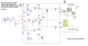
I have make some changes in the jfet input and the vas, the vas has higher id of 20 mA maybe it has even higher like 30 or even 50mA to prevent distortion in the drivers in relation with mosfet capacity, vbe multiplier is not simulate properly and has to be made in real, carefull!..
I will post sometimes progres and tests, but only simulation, people here can test it in real, I do that also but I have only scoop not THD meter.
We try to make it as simple as possible, less parts better sound, oneven harmonics weh have to fight even harmonic is of less problematic because it give music sometimes a nice body.
Attachments
Last edited:
hi kees52, what do you mean by "vertical output" in the thread's title - your schematic shows k1058/j162 which are not vertical but lateral MOSFETs ?
Also, the way you did cascoding of the input stage is suboptimal - Q1 and Q4 have too small Vds (0.2-0.3 V) to work properly. You should choose cascoding devices (Q5/Q6) with higher Vgs(off) like k246/j103 or you can raise gate potential of Q5/Q6 with voltage divider.
Not to forget, Vds(max) for 2sj108 is 25V and Q6 in your schematic works with Vds of about 35V - a risky strategy...
Last edited:
hi kees52, what do you mean by "vertical output" in the thread's title - your schematic shows k1058/j162 which are not vertical but lateral MOSFETs ?
Also, the way you did cascoding of the input stage is suboptimal - Q1 and Q4 have too small Vds (0.2-0.3 V) to work properly. You should choose cascoding devices (Q5/Q6) with higher Vgs(off) like k246/j103 or you can raise gate potential of Q5/Q6 with voltage divider.
Not to forget, Vds(max) for 2sj108 is 25V and Q6 in your schematic works with Vds of about 35V - a risky strategy...
Hi all
I have post the wrong schematic, and I now that the resistors are differend for both fets, but this has to try en measured in real time.
The cascode of j fets has advantages lower miller and more voltage, until now we have to keep voltage low, but I think we have to make the design more complicated, and put some fets in work, mirrors, ccs?
The j fets I have in schematic is because i have not much choice in multisim, the higher vgs jfets are not there, I will put them in and try the simulation again, and post itm or use enhanced mosfets with deviders as replacement..
Hmm be aware, I am not a scientist, but hobbyist like the most here, praktice do it not the school calculations is my experience..
First helping my friend, who has proberly cancer in his lungs, smoking habbits.
Attachments
Last edited:
Hi her a new version who has not the mentioned disadvances, the j fets get now a lower voltage and are cascoded with higher voltage mosfets, we call it version 2, it is nice playing with it, but make a amp very simpel with low distortion is not easy, maybe not possible.
Attachments
Kees,
Nice circuit, but symmetrical.
This tends to give odds higher than evens, and this is the reason the single ended approach was taken in the other thread.
Can you comment on your reasons for selecting this 'balanced' approach?
Cheers,
Hugh
There are fine amps with symetrical design, it cancels out the evens that is right, and let the odd intact, so you have to make a real symetrical amp by use components who have to be paired, that is however difficult with mosfets, the other tread use also symetrical output mosfets, and here it wil distroy the asymetrical approach, only the ZEN way works with a high current CCS, it is I think not always bad to get symetrical it is a lot used in practice, a clever approach is needed and I do combine already invented ideas, I am not so clever with the cosmetic words;-).
I will build this amp some day and look what it does with sound.
I have read something about od and even harmonics, but the science around it have some bottlenecks, a musician kan explaine that better then I can, music is a mix, the amp has only as task amplify it without put his own character in it.
Thanks for your attention.
Last edited:
Hmm old topic, but oke, blow some live in it.
The symetric solution has as al the balanced amps that give more odds harmonics, but I think that this is not the real problem with of a amp sound right or not, my opinion is still, high bandwith, only current feedback and much casode soultions, because compression and the voltage feedback give mucho problemens, we need to give amps air.
I like cascode tubes but the problem with them is S a lot are to weak, and so I use then penthodes in triode with high gm, the sound is then (dutch) luchtig.
Oke, I have did some experiments with the pc, and maybe you laugh all her, it healthy I now.
but see and let me now your thoughts about it, maybe it is already here somewhere, this idea is also candidate for hybride. canceling capacitance reduce distortion considerably.
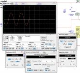
There a two schematics, one with 4 ohm load and one with 8 ohm load, the 4 ohm 194 watts, (watch distortion), but in real don,t try that, mosfets get stressed.
The symetric solution has as al the balanced amps that give more odds harmonics, but I think that this is not the real problem with of a amp sound right or not, my opinion is still, high bandwith, only current feedback and much casode soultions, because compression and the voltage feedback give mucho problemens, we need to give amps air.
I like cascode tubes but the problem with them is S a lot are to weak, and so I use then penthodes in triode with high gm, the sound is then (dutch) luchtig.
Oke, I have did some experiments with the pc, and maybe you laugh all her, it healthy I now.
but see and let me now your thoughts about it, maybe it is already here somewhere, this idea is also candidate for hybride. canceling capacitance reduce distortion considerably.
There a two schematics, one with 4 ohm load and one with 8 ohm load, the 4 ohm 194 watts, (watch distortion), but in real don,t try that, mosfets get stressed.
Attachments
Last edited:
Kees,
This is a fully symmetrical, fully cascoded PP AB power amp, using fets, mosfets and latfets throughout, but aside from competent design, high loop gain and low THD I can't see that it would sound much different to lots of other designs built with similar components. I'm also fairly sure it would have no image depth because of mosfet VAS and global feedback.
I guess these are obvious comments, but given your interest in tubes, why not stick to your original idea of a hybrid, and try to reduce the active component count?
I believe that the more complicated you make a circuit, the less DIYers build it. It reminds me of the inaccessible oil filter in a crowded automobile engine bay; it doesn't get changed enough, too expensive and difficult. A beautiful engine then gets a bad reputation for durability! Use NP's approach, keep it really simple, and put your effort into correct component choice and very precise dimensioning.
Sorry about the long post, didn't have time to write a short one!
Cheers,
Hugh
Hi Hugh
I do not only tubes but also i look sometimes on the alfet ones to test, the feedback is current in this one, I am still busy with the hybrides where I have a circlotron and a pp amp, oke, all have dc coupling and no feedback.
the circlotron go up to 500 Khz with tube drive.
Cascoding is a good way to avoid compression, therefore the sound go very easy that is why I did design this cascoded amp, it also go high, >1Mhz because of current feedback.
this can also without feedback, but need then degeneration, it is something for later, and I think bjt can sound even better in cascode form, symetrical is not bad, if use good components, elektuur do only make symtrical designs, but I agree glue two parts of a sinus together is not a nice idea, special high frequenties, single ended let the whole sinus intact.
Your post is alway educatief, so I like your long posts, I am a combiner of excisting amp inventions.
first I go make the excisting hybrid amp, I change the cathode mosfet driver for a plate mosfet driver with high current, then the amp has nothing anymore of feedback, and will listen, I have made a test mustage with 6C19P first I did use the 6AS7 but this one is to big needs to much current for class a.
you can see distortion here.
Attachments
Last edited:
Kees,
From where I stand, I think you have an open mind, and good electronics skills. I'm just trying to convey my general ideas, forged over a few decades and a lifelong interest in design.
Cascodes are generally used to extend HF response. In audio, they are useful to permit use of low voltage jfet input stages. I'm perplexed why you think they remove compression, but this is your experience - but it must be said they really increase the component count and can, with VAS circuits, reduce rail efficiency.
Designing for DC coupling is a good idea, but it can be taken too far, as again it can radically increase component count. We must keep our circuits simple, only when simple will they be built. And to make them simple takes more time, more care, and more inspiration, but the results can be very elegant. I'm a big fan of Jean Hiraga, Le Monstre is a masterpiece.
I have found that some people like single ended, even order distortions, some like symmetrical designs with predominating odd order, but few people like both. I prefer the SE approach; Borbely, as you rightly point out, preferred the fully symmetrical, complementary approach. We build what we like, that is certain.
On the tube front: Try using a simple plate loaded triode, direct coupled at the plate to the grid of a cathode follower. Use a double triode like an ECC81, since mu is around 50. You will find this sounds very, very good, has sufficient drive, and the sound quality can be manipulated slightly by increasing the CF tail resistor one standard value over the plate resistor. Power supply is not too critical with this approach since the current draw overall is fairly constant with signal.
I hope this is some help to you, you are a fine designer,
Groetjes,
Hugh
Maybe you have to read this (see downwards and pdf) signal compression is what we have to care for, so high impedance nodes maybe. See also in pdf. the amp down the pdf I have made in mosfet form. here I did get my idea from, so not completely mine.
I have a self bias tube cascode with 6SN7 on 450 volt, 10 mA idle, and the sound is really easy a lot of ear, because of a tube has not so high gm it is less suitable for cascode
but it do well, together with high impedance load like a cathode follower.
Cascodes in hf equipment I also now, it has high liniarity and bandwith and gain capacity is low and so it extence in HF amplification, and a lot because of cancel capacities.
I shure do differend tryouts, now I am trying penthodes with high gm , these with resistor loaded plate sounds not bad, the same with triodes all have high gm I like them.
and now I go remove the platefollower who drives the mosfets in dc mode, and repplace them with 6C19 high current tube in plate follower mode, in high idle. and go listen again, I think a
platefollower give more dynamics it lacks of feedback, I use a low mu tube to keep feedback free, with the mu circuit I get 2.4 x with a 6AS7 or a 6C19P and a lot of drive for mosfet..
I am shure everyone has his own ideas abouw what is best, but the best amp don,t excist (yet), I alway go listen to music in stores and party,s and then special with a lot of voices, I want my amp sounds the same, The elegantie about simple amps I also like, therefore I use tubes, a solid state what can do like a tube do, a single stage with enough amplification, also don,t excist.
a simple platefollower I use then always a gyrator, it is nog in signal path and it gives freedom tot the triode, that is wat i mean no compression.
I am sorry it is a whole story, and my english is not as good as yours, but accent is what make a person so interesting don,t you agree.
Afcourse I let you now.
listen to this peace of music, recorded with russian triode and gyrator on plate, very nice also, I have two there most are direct deleted when uploaded because of copyrights.. 6C4N-EB hybride - YouTube it has the 6C4N triode very good one also.
and so on and on, there is not much more top invent on audio amp teritory.
Thanks for your understanding.
While the distortion characteristics of a fully cascode amplifier are not
equivalent to those obtained through class-A operation, the lack of
signal compression produces a subjective '`ease" to the reproduced
sound that closely approximates that of the smooth nonlinearities which
characterize class-A operation and are achieved without the cost
penalties attendant to a class-A output stage.
I wish you a nice day, for me night.
Attachments
Last edited:
Hi Hugh, I think you like this more, it is quasy because I was a little curieus about semisouth, it need a big drive but this schematic go to 400 khz, easy, unfortanely it has a little feedback. And af course I have use dn2540 in the input, or other depletion fet, only the ccs needs adjusted then.
also this one I have made some weeks ago, not anymore because I am busy a lot with the tube hybrides and tests..
also this one I have made some weeks ago, not anymore because I am busy a lot with the tube hybrides and tests..
Attachments
Last edited:
- Status
- This old topic is closed. If you want to reopen this topic, contact a moderator using the "Report Post" button.
- Home
- Amplifiers
- Solid State
- JFET input, MOSFET VAS, VERTICAL output