Paulo, it seems your doing it right. The snubber needs to be next to the input transistor.
I don't know about CDIL parts but I've heard they're okay.
Best test for the input snubber is to do your input-finger test and adjust the input snubber until it did not happen. Use a large capacitor for the 20pF and a trimmer for the 3.3k; adjust trimmer until no radio noises and then lower capacitor as much as you can.
My only two qualms with the Circuit would be the Class B nature and need for extra electrolytics used. Has anyone found the quality of cap used affecting the subjective sonics?, probably not as much since there us a dc bias on all three of .6 v min. My design uses two more bjts, but only one e cap along with an adaptive bias open loop current buffer, of course there are many ways together to the same or similar result, but as mentioned prior, where current feedback excels is the mids and highs, just have to be aware of the series feedback resistor value otherwise if too high it's as bad as overcompensating with too much miller comp.
Colin
Colin
Last edited:
I believe your point one irrelevant for two reasons.My only two qualms with the Circuit would be the Class B nature and need for extra electrolytics used.
- The amp works in class A for normal listening levels.
- The problem of class B is distortion induced by the crossing. With current feedback amps, the speed is fast enough for the feedback suppress any issue. As thermal effects are more a concern, you will find an optimum bias, and notice that, ioncreasing-it will not improve the sound in anyway, but the contrary.
Point 2, you have other choices than electrolytic, in the signal or feedback path. On my side, i use film one for the input, and electrolytic in the feedback with no negative issue on the sound. Tried servo: no real change on the signature of the amp, and nothing witch destroy its transparent and fast aspect.
Esperado,
Fair enough, relying in feedback for correction, in any case it's a requirement. How would this amplifier do with electrostatics?, a difficult load and imagine it would change the flavour of sound with increasing phase shift and possibly stability issues. What kind of speaks are you driving with the ssa?.
Colin
Esperado,
How would this amplifier do with electrostatics?, a difficult load and imagine it would change the flavour of sound with increasing phase shift and possibly stability issues. What kind of speaks are you driving with the ssa?.
Colin
Remember that there are many versions of SSA!
Esperado's SSA-Crescendo is not as stable as other SSAs. My version (more or less VSSA) for example is the most stable among others. Incredible performance (phase behavior, Zout, etc) in LTSpice except for THD, which is about the average of SSA. Those with VAS cascode (BIGBT HP and SSA-Crescendo) have lower THD. SSA-Crescendo has very good sonic.
Jay,
How about on the ground, spice doesn't concern me as it all can go to hell in a hand basket once applied to a board, current feedback is very sensitive to layout and parasitics due to its speed. My concern is the sound with various loads, this is where a good current buffer comes into play, preferably out of the global loop.
Colin
Jay,
How about on the ground, spice doesn't concern me as it all can go to hell in a hand basket once applied to a board, current feedback is very sensitive to layout and parasitics due to its speed.
First, assuming that capacitive load modeling is relevant, some SSA is incredibly stable.
Second, some SSA is too simple to screw up. You can make a very short connection from output to input emitter and from stage to stage.
Third, I prefer to parallel the output mosfet, even tho one pair is enough to drive low impedance load. Fetzilla also has been reported to be able to drive low impedance load. I think it's of the same family.
If there is one point where usual sims are not relevant, this is it.First, assuming that capacitive load modeling is relevant, some SSA is incredibly stable.
And the reason is, with so fast and high bandwidth amps, the slighest parasitic capacitive load, induced by real/physical implantation can turn phase significantly (those parative caps are not taken in consideration in sims).
Reason, i believe, why L.C design & built his amps in real world, taking care of stability issues.
About Crescendo, i don't understand why you talk about this, but, how can you say something about its stability ? Did-you had build one ?
In the last private message i received about it in this forum, i quote: "...Now very stable under all conditions.".
If there is one point where usual sims are not relevant, this is it.
And the reason is, with so fast and high bandwidth amps, the slighest parasitic capacitive load, induced by real/physical implantation can turn phase significantly (those parative caps are not taken in consideration in sims).
Reason, i believe, why L.C design & built his amps in real world, taking care of stability issues.
About Crescendo, i don't understand why you talk about this, but, how can you say something about its stability ? Did-you had build one ?
In the last private message i received about it in this forum, i quote: "...Now very stable under all conditions.".
I don't have the need to measure stability of the real builds. Anyhow I pay attention to the simulated stability. And I still believe somehow that there is correlation.
I didn't say that SSA-Crescendo is not stable (no amp is 100% stable under all conditions anyway), I was comparing relative stability of SSA-Crescendo with other popular SSA and especially the VSSA. If you think this is wrong (that the simulated stability cannot be relied upon) then please give an expert analysis between any 2 SSA.
In the last private message i received about it in this forum, i quote: "...Now very stable under all conditions.".
I don't get it. Is there any change to the circuit or PCB?
Shaan knows how to make a good PCB layout. LC is even more with his very compact approach. The Crescendo PCB is terrible.
Jay, i would not like to be in a plane driven by a pilot only experienced as a flight simulator player.
Well, I build amps. I don't care how good or how bad amps are in simulations or even in measurements. I have faith in my ears. Simulators only tell me which amp to build.
If you can find people here who cares only with the real things, surprisingly it's me. I don't need to design my own amps if people can provide schematics as fast as I can build (and of course, I feel that I know how an amp should be built, I just not skillful yet to get it exactly perform the way I want it).
I have more than a hundred amps, but I tell you, none is enclosed in a box (I don't have time for doing PCB or boutique enclosure
 )
)(no amp is 100% stable under all conditions anyway.
Not entirely true, when you use a true open loop buffer designed correctly without its own loop feedback the reactive load of the speaker becomes invisible to the gain stage resulting in the need for minimal compensation. Also more importantly this can result in 100 percent stability into any load provided you can live with the sims of higher thd.
Colin
Hi everybody 
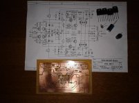
I decided to build SSA with BIGBT
I have some BC546 and BC556 with extremely close hFE 303 and 304 measure with normal DMM
BF471 and BF472 are not close hFE, 160 and 125,
Can i use common heatsink on both BF ?
On output i will use NJW1302 and NJW3281 with hFE 101 and 91
Suggestions are welcome
I decided to build SSA with BIGBT
I have some BC546 and BC556 with extremely close hFE 303 and 304
measure with normal DMMBF471 and BF472 are not close hFE, 160 and 125,
Can i use common heatsink on both BF ?
On output i will use NJW1302 and NJW3281 with hFE 101 and 91
Suggestions are welcome
Attachments
Last edited:
Hi everybody
I decided to build SSA with BIGBT
I have some BC546 and BC556 with extremely close hFE 303 and 304
BF471 and BF472 are not close hFE, 160 and 125,
Can i use common heatsink on both BF ?
On output i will use NJW1302 and NJW3281 with hFE 101 and 91
Suggestions are welcome
Yes you can use common heatsink for BFs, but it has to be on GND potential and both BFs isolated by means of mica/kapton washers. Be careful that it will be big enough to dissipate 2 W from both BFs at less than 50°C.
Inform us about results when finished.

I certainly willInform us about results when finished.
I like this combination of power transistors that form BIGBT, very interesting

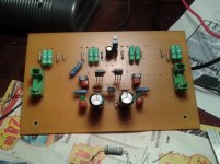
In the meantime some progress
Attachments
Last edited:
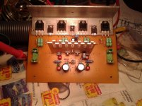
Job done !
Before i will power up this amp I have to check some things
- on the output I mount a Boucherot 10 ohm + 0.1uF
- i connect to GND L braket and BF's heatsink
- power supply is a half bridge SMPS that i made two months ago, +/-58v with no load
- what is the optimum bias for BIGBT output?
If you already explained about bias the BIGBT i apologise, but there are 400 pages to read and i can't wait to power up this amp
Before i will power up this amp I have to check some things
- on the output I mount a Boucherot 10 ohm + 0.1uF
- i connect to GND L braket and BF's heatsink
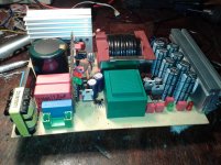
- power supply is a half bridge SMPS that i made two months ago, +/-58v with no load
- what is the optimum bias for BIGBT output?
If you already explained about bias the BIGBT i apologise, but there are 400 pages to read and i can't wait to power up this amp
Attachments
Last edited:
Very nice looking PCB, just great.
Well VAS/TIS TO-126 should have 10-12 mA bias, each output BJT 100 mA, and IRFs will consequently set up at 30 mA if you use 22 ohm Rbe for the outputs.
SSA is completely DC coupled so expect some DC offset traveling if you don't have some sort NTC, DC servo or other temp tracking for the input stage. Bias spreader for the outputs sense and regulates only main heatsink conditions.
Regards, L.C.
BTW cool SMPS you have there.
Point 2, you have other choices than electrolytic, in the signal or feedback path. On my side, i use film one for the input, and electrolytic in the feedback with no negative issue on the sound. Tried servo: no real change on the signature of the amp, and nothing witch destroy its transparent and fast aspect.
Try a bipolar electro in place of polar-electro. they offer better meaureable performance in low thd audio circuits.
Thx-RNMarsh
- Status
- This old topic is closed. If you want to reopen this topic, contact a moderator using the "Report Post" button.
- Home
- Amplifiers
- Solid State
- Simple Symetrical Amplifier