???
Please, use 1K in serial and 50 or 100pf to the ground. Are your speaker's cables long ?
I prefer not to use over 1 meter cable ( I always kept below 1 meter)

Just a curious, what is the relationship of adjusting the resistance against capacitance if we kept the cutoff frequency constant ? (example: what is the difference between using 1ohm &1uF against 1k ohm & 100pF ? )
Hey Shaan, I never saw you have those links below your post (signature I believe) Its a great job putting those together and compile it, thanks you ! LC would have save alot of job if I were to see those early ! (I just have so much question to ask ^^)
Last edited:
Hi LC.. sorry for late answerCompared to some commercial amp? Did you like it? Which speakers?
I don't have any commercial Amp, it cost to high for me and speaker i use just DIY entry level speaker.. build by local senior DIYer.
I do compare with other great design Amp i've build from this great site.
i'm very satisfied with my Shan's SSA build
... such big sound coming from small Amp, nice treble, nice bass, clear vocal... no hum, no hiss.. play all music genre vocal, instrument, pop, rock, metal, jazz PS:
i've upgrade my VAS Tr using 1360/3423 and more smooth treble.
 Hope the links help you on your way to building your own SSA.
well, what I mean is that what is the difference between using those different combination ? (while we still get the same Low Pass Cutoff Frequency)If you double series resistance, halve shunt capacitance. Triple resistance, divide capacitance by 3. And so on. This way LP corner will stay the same.
Example: combination of high resistance & low capacitance will get what result ? affect phase or anything else ?
Thanks for your explanation and advise, didn't realise it before.Hi guitar89. By using 1ohm/1uF instead of 1k/100pF you are going to kill your signal source brutally. With low R and high C you demand high AC current from the source. Best is to use 1k/100pF and it won't cause any sonic degradation.
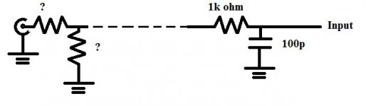
Would it be wise to integrate a volume pot after these filter ? could it be put before the filter (nearer to source)? (or is there anyway to make it foolproof of putting pot)
Just curious, what if I raise more resistant and less capacitance ? example of 10k ohm and 10pF. (My guess is low source input ?)
Would it be wise to integrate a volume pot after these filter ? could it be put before the filter (nearer to source)? (or is there anyway to make it foolproof of putting pot)
The RC lowpass filter should be as close as possible to the bases of the input BJTs, i.e. nothing between filter and SSA. This is foolproof enough.
Just curious, what if I raise more resistant and less capacitance ? example of 10k ohm and 10pF. (My guess is low source input ?)
The result is audible noise and poor frequency response, as SSA demands a low impedance source to work at its best and the 10k just adds itself up with the nominal output impedance of the source resulting into very low available drive current for an amp with 10k input impedance such as SSA, not good.
Last edited:
Ok, I will kept the minimum at front. What value of pot is recommended with this filter ? (in order not to reduce input drive current too low)The RC lowpass filter should be as close as possible to the bases of the input BJTs, i.e. nothing between filter and SSA. This is foolproof enough.
The result is audible noise and poor frequency response, as SSA demands a low impedance source to work at its best and the 10k just adds itself up with the nominal output impedance of the source resulting into very low available drive current for an amp with 10k input impedance such as SSA, not good.
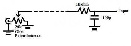
(As in my attachement ?)
Attachments
I guess the previous sketch isn't nice and exact, so this attachment should be perfectly fit your description ?Use a 20k pot. One end to source, other end to ground and the slider to SSA.
Regards,
Leong
Attachments
Ok, I know what value should I use, but is there any specify material to use ? for resistor, pot and cap.
Sometimes people say avoid mica, wirewound or something else, what should I pick, or what should I avoid ?
I have no experience buying 'better' potentiometer, what type/brand should I buy for reliable ? (no need for top-notch performance, but fairly good/worthy ones)
I only buy dirt-cheap type before, which over few month you can heard noises from adjusting.
guitar89, caps in the signal path are, indeed, critical. You can use in order of quality, and if they are available:
- Film caps with polypropylene dielectric
- Other film caps
- Tantalum caps, but they need to be polarized in such a way that DC always remain > 3V whatever the signal is negative at full excursion.
- Electrolytic caps with the same precaution but less margin (they just need to never reverse). Use Low ESR models, in a high impedance circuit. When non polarized ones are used, take a BIG margin for voltage.
Avoid any ceramic (they are ok for decoupling), as they are resonant.
To Know all, or near about cap's quality for audio:
Picking Capacitors - Walter G. Jung and Richard Marsh
For PSUs, where you need Electrolytics for big values, a good solution is to use paralleled little values instead of a big one: their parasitic resistance and inductances will be divided by their numbers, and little capacitances present less of those individually.
About Pots, they, indeed generate little distortion and noise. Less you ask current from them (Charge them with FETs,) better it is. The best choice for audio, at the moment is ALPS.
A better solution is to use a muti-position rotating switch with array of metal film resistances.
Or to use a PGA23xx circuit (my preference).
For resistors, use metal thin film ones for signal path (wirewond ones to be reserved for PSUs) . More the resistances heat, more they create distortion: take a big power margin.
This is specially important for the feedback serial resistance, because their distortion will be applied to the feedback loop, when you want a perfect mirror of output: take audiophile parts here. (the only situation where i suggest an audiophile part A good solution can be parallel devices here.
- Film caps with polypropylene dielectric
- Other film caps
- Tantalum caps, but they need to be polarized in such a way that DC always remain > 3V whatever the signal is negative at full excursion.
- Electrolytic caps with the same precaution but less margin (they just need to never reverse). Use Low ESR models, in a high impedance circuit. When non polarized ones are used, take a BIG margin for voltage.
Avoid any ceramic (they are ok for decoupling), as they are resonant.
To Know all, or near about cap's quality for audio:
Picking Capacitors - Walter G. Jung and Richard Marsh
For PSUs, where you need Electrolytics for big values, a good solution is to use paralleled little values instead of a big one: their parasitic resistance and inductances will be divided by their numbers, and little capacitances present less of those individually.
About Pots, they, indeed generate little distortion and noise. Less you ask current from them (Charge them with FETs,) better it is. The best choice for audio, at the moment is ALPS.
A better solution is to use a muti-position rotating switch with array of metal film resistances.
Or to use a PGA23xx circuit (my preference).
For resistors, use metal thin film ones for signal path (wirewond ones to be reserved for PSUs) . More the resistances heat, more they create distortion: take a big power margin.
This is specially important for the feedback serial resistance, because their distortion will be applied to the feedback loop, when you want a perfect mirror of output: take audiophile parts here. (the only situation where i suggest an audiophile part
A good solution can be parallel devices here.
Last edited:
guitar89, caps in the signal path are, indeed, critical. You can use in order of quality, and if they are available:
- Film caps with polypropylene dielectric
- Other film caps
- Tantalum caps, but they need to be polarized in such a way that DC always remain > 3V whatever the signal is negative at full excursion.
- Electrolytic caps with the same precaution but less margin (they just need to never reverse). Use Low ESR models, in a high impedance circuit. When non polarized ones are used, take a BIG margin for voltage.
Avoid any ceramic (they are ok for decoupling), as they are resonant.
To Know all, or near about cap's quality for audio:
Picking Capacitors - Walter G. Jung and Richard Marsh
For PSUs, where you need Electrolytics for big values, a good solution is to use paralleled little values instead of a big one: their parasitic resistance and inductances will be divided by their numbers, and little capacitances present less of those individually.
About Pots, they, indeed generate little distortion and noise. Less you ask current from them (Charge them with FETs,) better it is. The best choice for audio, at the moment is ALPS.
A better solution is to use a muti-position rotating switch with array of metal film resistances.
Or to use a PGA23xx circuit (my preference).
For resistors, use metal thin film ones for signal path (wirewond ones to be reserved for PSUs) . More the resistances heat, more they create distortion: take a big power margin.
This is specially important for the feedback serial resistance, because their distortion will be applied to the feedback loop, when you want a perfect mirror of output: take audiophile parts here. (the only situation where i suggest an audiophile part
I have 2 of these little cute thing in stock: 100pF Capacitor
About the Potentiometer, I just oredered them before I look into this thread: Alps 20k Potentiometer
Just coincidencely brought alps ^^ although cheap ones
About the Stepped Attenuator, I would like to save cost, so means DIY, but it seems complicated for me to accomplish nicely. I prefer analog ^^ Another option I had heard is about LDR type of attenuation.
You can forget about them: good enough parts are not available, need to be carefully matched (need a lot of samples) and, whatever , will present too much distortion, comparing to the PGA23xx.Another option I had heard is about LDR type of attenuation.
You can find cheap Chinese of those last ones, that you can enhance to the top with few modifications, like removing electrolytic caps or little changes of ground paths:
4 Ways Stereo Remote Volume Control Motorized ALPS Potentiometer, Stand-By Board eBay Boutiques | HiAmplifier Audio Store
Last edited:
- Status
- This old topic is closed. If you want to reopen this topic, contact a moderator using the "Report Post" button.
- Home
- Amplifiers
- Solid State
- Simple Symetrical Amplifier