You better listen, in order to set the best power biasIn my opinion would be 100 mA enough to the end Fets and 15 mA to the Cascodes. What value of Bias would be useful for the driver Fets M9 and M10?
I can change the current through the cascode, by two Ways: First: I change the value of Resistors R9 and R12 (270 Ohm). second: I change the value of the Cascode -Resistors R16 and R18 (10 Ohm). What would be the better way?
Best regards Gerd
") On my preference, it is often around 150ma.
On my preference, it is often around 150ma.About the cascode, just set-it for enough current to feed the parasitic capacitance of M9/M10. I believe 14ma is enough for a good slew-rate.
About the way to change the current in the cascode, i use 2 methods, first to change the current of the input stage. It will change the voltage across R9 - R12. Changing the values of R9 - R12 do the same, but will change the gain of the first stage, so the open loop gain, right ? The best is to simulate for the best distortion. Takes some times playing with this or that, not so easy...
I am curious to see the answers of LC to those questions.
Just verify there is at least 1/4 of the current of the output devices ?150 mA for the FET drivers M9/M10 to ?
I am also looking forward to answering LC
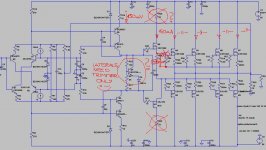
Caution, I believe there is a mistake at output of the M9 on your schematic: Don't it has to be connected to the common path of the 47 Ohms ?
Last edited:
I am curious to see the answers of LC to those questions.
I am also looking forward to answering LC
Attachments
Can-you comment ? (means: How do-you manage your choices of gain/current of the different stages, specialty input and VAS ?).
Well seen about the temp compensation that i had not noticed: Laterals have a negative temp behavior, so such a stage is not needed and worsen the characteristic.
Last edited:
Hi coolewater
Please make all changes marked with red on sch I posted.
Regarding 15 mA VAS (cascode) bias current, you must not change any of mentioned resistors, since they're in direct relation to OLG (open loop gain).
15 mA VAS bias current you can set with adjusting (trimming) 10 mA current source/sink in input stage.
BR LC
Any comment about my question, a problem i'm always asking myself when i design a power amp. How to manage the relative gain in the various stages of the OLG and their currents. I have spend a lot of time simulating different solutions, no evidences yet(assuming current are enough for class A, of course) .
Marry Christmas to everybody
@ LC @
I wish You a really nice day today when .. .. is visiting You
to bring You lot's of new & refreshing inspirations and as
we already got lot's of Yours nice 'Gifts' . . . I'm sure that more to come ...
I wish You a Marry Christmas
& the same wish to everybody here . . .
Andreas
@ LC @
I wish You a really nice day today when ..
.. is visiting You to bring You lot's of new & refreshing inspirations and as
we already got lot's of Yours nice 'Gifts' .
. . I'm sure that more to come ...I wish You a Marry Christmas
& the same wish to everybody here . . .
Andreas

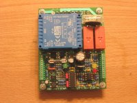
WOW how many connector's pins just for a controlled inrush sequence. Over engineered?
BTW nicely put together, good job.
Thanks. It has not only soft start (current inrush limiting) function, but many more: 12V trigger in/out, push button switch, remote control and even option for DC detection circuit.
Another great design LC
Thanky you Andreas
Marry Christmas to you and to all dear friends from the forum.
Andrej
To All Music & Sound Lovers
I Wish a Happy New Year 2013
Andreas
Attachments

Error correction
Happy new-year for all of you, SSA friends.
For this new year, would-you be interested to explore a way to reduce by ~20db the distortion of your SSA amplifier ?
(It had something to do with my (orphan) protection circuit and DC servo:
http://www.diyaudio.com/forums/solid-state/221737-ultimate-amp-protection-circuit.html#post3254403
No change of the amp itself, before is in red, after in green.
Attachments
Happy new-year for all of you, SSA friends.
For this new year, would-you be interested to explore a way to reduce by ~20db the distortion of your SSA amplifier ?
(It had something to do with my (orphan) protection circuit and DC servo:
http://www.diyaudio.com/forums/solid-state/221737-ultimate-amp-protection-circuit.html#post3254403
No change of the amp itself, before is in red, after in green.
good investigation.Happy new-year for all of you, SSA friends.
For this new year, would-you be interested to explore a way to reduce by ~20db the distortion of your SSA amplifier?
Happy New Year dear Esperado.

Of course I/we would be interested for great improvement, if such good idea is wise to reveal at all. Maybe you could make more out of it if not publish it here but rather in good idea's office.

Time out for suspense
It used an idea i had several years ago, refreshed by the reading of: http://hifisonix.com/wordpress/wp-content/uploads/2012/12/AFEC-V1.0.pdf (By one of our good members: Bonsai).
I had set-it for exploration with those concerns:
Use of OPAs in current-feedback, to stay in the SSA spirit and because we need here very fast OPA, to reduce HF phase errors as much as possible.
This imply the Amp Out had to be plugged in the - side (low impedance) of the comparator (U2). So we will need to invert the phase of the result with the next OPA (U1) .
Of course, you can use a very fast voltage feedback OPA as well, but they are harder to find.
The gain of the firt OPA is st to go near the rails with the max input signal's level. This, in order to minimize the clipping bad behavior of this Error correction technology. But a hard clipping before the input would be a good (better) response too.
The R10 has to be carefully adjusted in order to minimize the output level at 100 Hz (to avoid any phase problem). In real life, it will be a trimer.
Then, at 3Khz, C22 has to be adjusted to reduce the same level (compensation of the Power amp's delay at HF).
At the end, you will adjust the overall gain of U1 to get the best distortion/ stability result.
It is possible to go further, but it will be a little tricky.
The overall idea is to isolate the distortion, comparing out and in of the power amp, like in my protection circuit. This error will be added in the feedback loop, reducing further the original distortion without changes of the overall open loop and closed loop gain.
An other advantage is this will help to set the offset, as it works like a DC servo.
Do not care about some strange useless resistances here or here, they are to help-me to explore different things and cut some wires easily.
Up to you all to play with this idea.
It used an idea i had several years ago, refreshed by the reading of: http://hifisonix.com/wordpress/wp-content/uploads/2012/12/AFEC-V1.0.pdf (By one of our good members: Bonsai).
I had set-it for exploration with those concerns:
Use of OPAs in current-feedback, to stay in the SSA spirit
and because we need here very fast OPA, to reduce HF phase errors as much as possible.This imply the Amp Out had to be plugged in the - side (low impedance) of the comparator (U2). So we will need to invert the phase of the result with the next OPA (U1) .
Of course, you can use a very fast voltage feedback OPA as well, but they are harder to find.
The gain of the firt OPA is st to go near the rails with the max input signal's level. This, in order to minimize the clipping bad behavior of this Error correction technology. But a hard clipping before the input would be a good (better) response too.
The R10 has to be carefully adjusted in order to minimize the output level at 100 Hz (to avoid any phase problem). In real life, it will be a trimer.
Then, at 3Khz, C22 has to be adjusted to reduce the same level (compensation of the Power amp's delay at HF).
At the end, you will adjust the overall gain of U1 to get the best distortion/ stability result.
It is possible to go further, but it will be a little tricky.
The overall idea is to isolate the distortion, comparing out and in of the power amp, like in my protection circuit. This error will be added in the feedback loop, reducing further the original distortion without changes of the overall open loop and closed loop gain.
An other advantage is this will help to set the offset, as it works like a DC servo.
Do not care about some strange useless resistances here or here, they are to help-me to explore different things and cut some wires easily.
Up to you all to play with this idea.
Attachments
Last edited:
- Status
- This old topic is closed. If you want to reopen this topic, contact a moderator using the "Report Post" button.
- Home
- Amplifiers
- Solid State
- Simple Symetrical Amplifier