I was thinking from an industrial point of view: So many of the amps on the market use near the same input pair, most on both differentials. it is A LOT of devices.How much of us need the matching properties of PNP and NPN? How much is our purchase in a year?
In my research and development office, we would had compared the price to pair 2 transistors VS the price of a ready to use matched pair with better temp balance.
Manufacturers could take a part of the difference, increasing their benefits.
Well, it was the good old time.
Last edited:
Hi LC,
Thank you so much for your comments. I'll do all those changes that you've mentioned.
The CCS you've designed is a bit spohisticated, probably that will require an "add on" board like the one you've designed. I've checked from the local market for components and those matched transistors (SSM 22xx) parts are unbotanium here. Will a matched BC's or similar transistors work with this scheme...? or else can you suggeest alternative parts.
Magma, i believe you can set those CSS on board as well, i believe Lazy CAT did a separate board for them to can reuse them on future projects and developments.The CCS you've designed is a bit spohisticated, probably that will require an "add on" board like the one you've designed. I've checked from the local market for components and those matched transistors (SSM 22xx) parts are unbotanium here. Will a matched BC's or similar transistors work with this scheme...? or else can you suggeest alternative parts.
Why don't you try Mouser of Farnel, if you cannot get the parts locally ?
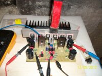
And here it is. Running smoothly.
Offset setting was pretty easy; within +-5mV.
Bias perfect with 3mA, 14mA and 160mA in input, VAS and FET respectively. Without any manual setting. The input BJTs are BC550C and BC559C.
Sounds just like an SSA.
Hmm... peeceebee works for me too...

Hi Shaan

Finally SSA BASIC PCB for you, congratulations. Looks you've designed layout well since there's no sound difference compared to test boards. Only thing that bothers me is a question why you never connect output transistors pins directly to PCB?

Regarding CCS compared to current injection resistor to input stage, I can assure you that using fet cascoded CCS is more correct and musical than resistor. Because we are dealing here with input stage where uA-s have big signature we have to use best CCS, simple two BJT CCS is simply not enough accurate for the job. Modulation suppression vs. freq bandwidth, noise, thermal stability all are very important for SSA input stage CCS, that's why I choose the one proposed in post #3034.
Hopefully you'll test one like in the future and share opinion. Best regards L.C.

Hello, I am following with great interest SSA . I have provisionally
SSA established an Amp. Unfortunately, there is a problem.
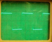
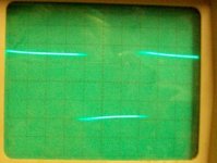
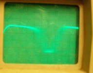
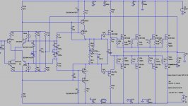
The amp only worked up to a supply voltage of + - 35 volts properly. I increased the gate resistors to 220 ohms, and the capacitances between the base and emitter of the T8 and T11 increased to 47PF. The 3db frequency is reduced to 500 Khz. The amplifier is now working to + - 45 volts properly. From about + - 50 volts, the amplifier oscillates. But I have a transformer with 600 watts + and - 55 volts, which I would like to use. The amp is loaded with 8 ohms. The oscilloscope is set with 5Volt/cm. The frequency of the test signal is 10kHz. What else can I do? Are there any oscillations? or is anything limited.
Thanks Gerd
SSA established an Amp. Unfortunately, there is a problem.
The amp only worked up to a supply voltage of + - 35 volts properly. I increased the gate resistors to 220 ohms, and the capacitances between the base and emitter of the T8 and T11 increased to 47PF. The 3db frequency is reduced to 500 Khz. The amplifier is now working to + - 45 volts properly. From about + - 50 volts, the amplifier oscillates. But I have a transformer with 600 watts + and - 55 volts, which I would like to use. The amp is loaded with 8 ohms. The oscilloscope is set with 5Volt/cm. The frequency of the test signal is 10kHz. What else can I do? Are there any oscillations? or is anything limited.
Thanks Gerd
Attachments
Gerd, VAS directly loaded with 3 pairs of mosfets simply doesn't have enough current capability to drive mosfet's input capacitance plus load at full scale 10kHz squares. Intermediate driver (mosfet or BJT) would certainly help.
First you can also:
- try to observe 10 kHz squares with/without load connected
- try to use one pair of output mosfets to see if the situation is still the same
- compensate each output mosfet with serial zobel between gate and drain
If any upper measure would not help, than you'll need to install the driver stage between VAS and the output mosfets.
Lazy cat, may-i suggest-you to post measurements of your amps ?
HD, IM and bandwidth ?
There is surely a visible benefit with the use of your CSS.
About the CSS, it would be interesting to show what's happens at their outputs at Hf (1Mhz) while full signal in the amplifier ?
Coolwater, while you fight with stability problems, may-i suggest-you few tips ?
First to try to increase the open loop bandwidth as much as possible, means reduce as much as possible the miller caps.
You can work on the output zobel and a cap // to the serial resistances of the feedback path to tune the phases.
An inductance in output can help too, if the problem is too much capacitance in the load.
If you use a simulator, in order to track the problems, do not forget to remove the input filter cap, when you track the phases.
Hoping it will help.
Last edited:
You can tune-it for no overshoot à 1Khz for small signals as well as half the power.Hello Esperado, a good idea, thank you. A trimming capacitor in parallel to the serial resistances of the feedback path to tune the phases. I try it .
The reason to reduce the miller is to keep the open loop bandwidth as high as possible. It has a direct impact on the quality.
Why you never connect output transistors pins directly to PCB?
Hi LC.
The wires are for testing different pair of LATFETs in the same board, with as less mess as possible. Under-board aesthetix.
The gate wires have two 100ohm stoppers at each end, one on-board, another on FET.
The final assembly will not have these ugly wires; what's the meaning of having a peeceebee if putting wires here and there?
Hello Esperado, Hello LC,
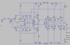
I have removed all 47pF Kapacitors. I tuned the phases with a a trimming capacitor in parallel to the serial resistances of the feedback path. I had a perfect rectangular signal. When I switched to a second pair of MOSFET were the oszillations again. I will turn to a driver stage. One more question: What the resistors R8 and R10 effect at 1.2 K? In my opinion, provide the resistors Transisoren the Q1 and Q2 with current when the output signal is 0 volts. Is that correct?
I have removed all 47pF Kapacitors. I tuned the phases with a a trimming capacitor in parallel to the serial resistances of the feedback path. I had a perfect rectangular signal. When I switched to a second pair of MOSFET were the oszillations again. I will turn to a driver stage. One more question: What the resistors R8 and R10 effect at 1.2 K? In my opinion, provide the resistors Transisoren the Q1 and Q2 with current when the output signal is 0 volts. Is that correct?
Hi,
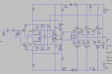
the final version of my SSA Mosfet. The PCB is in the works. A Question to the Bias:
In my opinion would be 100 mA enough to the end Fets and 15 mA to the Cascodes. What value of Bias would be useful for the driver Fets M9 and M10?
I can change the current through the cascode, by two Ways: First: I change the value of Resistors R9 and R12 (270 Ohm). second: I change the value of the Cascode -Resistors R16 and R18 (10 Ohm). What would be the better way?
Best regards Gerd
Attachments
- Status
- This old topic is closed. If you want to reopen this topic, contact a moderator using the "Report Post" button.
- Home
- Amplifiers
- Solid State
- Simple Symetrical Amplifier