Hi jay,
What would be the "ideal" bias? About 17ma current flows across the resistor with the current setup(+/-75v)....Is it too high?
Shaan,
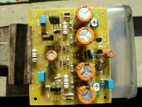
Thanks for the kind words. I've chosen keltron caps for most locations except for the main decoupling caps. In my experience these caps are much better than the regular samwa types, known for leakage at its early life span. Of course these caps cost atleast twice more than samwa here in the local market.
Everything worked to my expectation, except the dc offset, which goes up / down (+ / - 50mv).
Once i get this sorted out, planning to test the amp in a PA system to explore further on this amp. will post my results soon...
What would be the "ideal" bias? About 17ma current flows across the resistor with the current setup(+/-75v)....Is it too high?
Shaan,
Thanks for the kind words. I've chosen keltron caps for most locations except for the main decoupling caps. In my experience these caps are much better than the regular samwa types, known for leakage at its early life span. Of course these caps cost atleast twice more than samwa here in the local market.
Everything worked to my expectation, except the dc offset, which goes up / down (+ / - 50mv).
Once i get this sorted out, planning to test the amp in a PA system to explore further on this amp. will post my results soon...
Hi jay,
What would be the "ideal" bias? About 17ma current flows across the resistor with the current setup(+/-75v)....Is it too high?
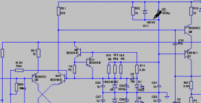
Hi, I just noticed your circuit is different than the one used in BIGBT HP. If I'm not mistaken your approach has been used by Shaan. The 17mA you mentioned is flowing to the regulator. The input itself is biased less than that. Around 8mA I guess.
I think there is nothing wrong with "hot" regulator (as long as there is sufficient heatsinking). I don't know about the "optimum" bias for the input. I have used around 10-12mA.
ADD: May be Shaan has a comment regarding this regulator (CCS). I think he didn't use it at the end.
Attachments
Last edited:
Hi all,
After a month's work, finally got my version of SSA singing...")
Is your sch exact from post #3550 or it is modified?
Regards L.C.
Hi jay,
Thanks for your suggestions. yes, the circuit is based on shaan's version, except the CCS which i intend to keep to improve PSSR. I'll try to modify the bias to 10 - 12 ma and see if it affects the sound. I'd like to keep the sound as it is....
Hi LC,
Its the same circuit as shown in the post 3550....
Hi jay,
Thanks for your suggestions. yes, the circuit is based on shaan's version, except the CCS which i intend to keep to improve PSSR. I'll try to modify the bias to 10 - 12 ma and see if it affects the sound. I'd like to keep the sound as it is....
As you can see it is also Lazy Cat's version from year before.
If you like I can comment your sch later today. Otherwise very professional SSA you have made.

What would be the "ideal" bias? About 17ma current flows across the resistor with the current setup(+/-75v)....Is it too high?
IMO, the amount of current needed to flow through the input pair for a VAS current of 10mA at +-65V in your case would be "ideal". It could be as low as 1mA into the input trannies. Measure the VAS bias and if it's about 10-15mA then all's well.
Shaan,
Thanks for the kind words. I've chosen keltron caps for most locations except for the main decoupling caps. In my experience these caps are much better than the regular samwa types, known for leakage at its early life span. Of course these caps cost atleast twice more than samwa here in the local market.
Ya, I discarded those samwha caps a couple of years ago and now use Keltron for all my DIY jobs. Double the price no doubt, but solid performance.
Everything worked to my expectation, except the dc offset, which goes up / down (+ / - 50mv).
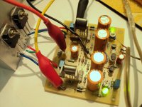
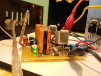
It should not if the input pair is thermally coupled with a cable tie(zip tie) and a drop of heatsink paste. In the picture it looks like the input pair and the cascodes are well placed(face to face) but the center two transistors(possibly the input pair) aren't tied together. I think this is causing you the offset problem.
Also the schematic shows no 10K from the conjoined bases of the input pair to ground. This could also cause offset problems due to lack of base current at the inputs.
Once i get this sorted out, planning to test the amp in a PA system to explore further on this amp. will post my results soon...
Lookin' forward.
The 17mA you mentioned is flowing to the regulator. The input itself is biased less than that. Around 8mA I guess.
Yes. Most of it flows to ground through the 100ohm resistors. My setup has 3.5mA through the input BJTs, but total 12mA from the +-15V zener supply.
May be Shaan has a comment regarding this regulator (CCS). I think he didn't use it at the end.
It sounded bad. It didn't have the collectors of the voltage sense transistors sinked/sourced to/from ground, but floating. This definitely is an example of bad design resulting into bad sound. I will connect it again soon with corrected design. Hope to have good results.
shaan's version
It's based on LC's SSA as the VAS has cascodes. My PS is +-28VDC, so cascodes there is a no-no.
But, maybe in future, with +-56V... We'll see.
Last edited:
Hi LC,
Thanks LC. Its my pleasure, to have your comments on the scheme....i'm sure that will certainly improve the performance of the amp further.
Hi Shaan,
I'll take your views on bias....i'll try to couple all the input trannies with heatsink compound....perhaps that could solve the DC drift problem....i do have the 10k input bias resistor in place with this amp
How do i reference the CCS to ground with this design....any idea?
Will that have positive influence on the overall sound quality of the amp...?
I'm already very happy with the sound....
Do you think a simple resistor bias is better than the CCS, especially the PSRR and of course sound quality as well...what's your experience...? probably i'll also experiement with that....
Hi Shaan,
How do i reference the CCS to ground with this design....any idea?
Your CCSs are already sourced/sunk to/from ground. Mine was not.
Will that have positive influence on the overall sound quality of the amp...?
I can't say for sure, but I must first try it myself before deciding over its influence on sonics. The floating nature of the CCS I built is my suspect for the fatiguing sound.
Do you think a simple resistor bias is better than the CCS, especially the PSRR and of course sound quality as well...what's your experience...? probably i'll also experiement with that....
Tough question.
It's easy to understand that CCS will improve the precision of the feedback network at HF by an order of magnitude than that with a resistor. Probably the PSRR will also be higher with CCS. but,
BUT
what if your brother or friend likes the "precise" sound but you don't???
If you like the sound and it doesn't give you fatigue then no matter whether its a CCS or a resistor, it's perfect.
Well, my SSA's FB network is fed through two 1K2 resistors and this amp sounds more precise to my ears than any other amp I have heard, right up to full volume. It has stunned more than 100 people with its sound(me included) to-date and is keeping up the shock-job for new people almost every week.
No hum no noise no no instability no fatigue so far.
My SSA is made for music, and its music says it's true.
That said, there is no guarantee that you will like the resistor-fed SSA sound more than the CCA-fed SSA. Here's the devil, subjective quality, totally private property.
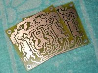
I finally got my first PEECEEBEE and first ever PCB. Can you imagine?
My local DIY friend Bhaskar has printed six SSA boards. Yesterday I was on a visit to his home and had some unique experiences.
First, he's a genuine music-lover; has over 3000 pieces of gramophone records and most of them are pure gem recordings. Many dating to 65's! I had my first experience of listening to analog recording and I was completely blown away. The realistic feeling of the music just froze me and now I know why people say that once you get into analog, there's no coming back.
Second, he is a very kind person. He provided me with two of the six SSA boards made and now I have my own designed peeceebee at hand.
The peceebees look very well etched without any errors.
Now I'm on the way to build a pair of SSAs in the pro way LOL.
Thanks for the good wishes all.
Attachments
Wow.. nice peeceebe finally you have your own boardMy local DIY friend Bhaskar has printed six SSA boards. Yesterday I was on a visit to his home and had some unique experiences.
First, he's a genuine music-lover; has over 3000 pieces of gramophone records and most of them are pure gem recordings. Many dating to 65's! I had my first experience of listening to analog recording and I was completely blown away. The realistic feeling of the music just froze me and now I know why people say that once you get into analog, there's no coming back.
Second, he is a very kind person. He provided me with two of the six SSA boards made and now I have my own designed peeceebee at hand.
The peceebees look very well etched without any errors.
Now I'm on the way to build a pair of SSAs in the pro way LOL.
Thanks for the good wishes all.
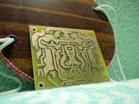
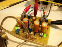
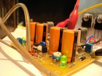
And here it is. Running smoothly.
Offset setting was pretty easy; within +-5mV.
Bias perfect with 3mA, 14mA and 160mA in input, VAS and FET respectively. Without any manual setting. The input BJTs are BC550C and BC559C.
Sounds just like an SSA.
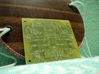
Hmm... peeceebee works for me too...
Offset setting was pretty easy; within +-5mV.
Bias perfect with 3mA, 14mA and 160mA in input, VAS and FET respectively. Without any manual setting. The input BJTs are BC550C and BC559C.
Sounds just like an SSA.
Hmm... peeceebee works for me too...
Attachments
Magna's SSA HP for PA
Hi Magna
Comments as I promised:
- Q3, Q5 must be firmly thermally coupled, glued or grease + wraps
- input CCS-s should be top quality with thermally independent reference as in #post 3034. Replace Q8, Q11, Q12, Q13 with reference CCS-s
- C7, C62 lower to 100 uF
- C10, C34 remove these 47 pF caps, install trimmer-caps and find optimal sweet spot between lower and higher freq oscillation
- C16, C18 higher to 1000 uF
- optimally and effectively front-end should have 5 V higher rails than output stage
- C1 should be 10 uF, C5 100 pF
- D1, D13 recommend to change to 1N4732 - 4,7 V
You can fill in the whole 5 output pairs on PCB for 2 ohm loads capability.
Looking forward to see your modifications and reports.
Hi LC,
Thanks LC. Its my pleasure, to have your comments on the scheme....i'm sure that will certainly improve the performance of the amp further.
Hi Magna
Comments as I promised:
- Q3, Q5 must be firmly thermally coupled, glued or grease + wraps
- input CCS-s should be top quality with thermally independent reference as in #post 3034. Replace Q8, Q11, Q12, Q13 with reference CCS-s
- C7, C62 lower to 100 uF
- C10, C34 remove these 47 pF caps, install trimmer-caps and find optimal sweet spot between lower and higher freq oscillation
- C16, C18 higher to 1000 uF
- optimally and effectively front-end should have 5 V higher rails than output stage
- C1 should be 10 uF, C5 100 pF
- D1, D13 recommend to change to 1N4732 - 4,7 V
You can fill in the whole 5 output pairs on PCB for 2 ohm loads capability.
Looking forward to see your modifications and reports.
No good enough npn-pnp matched pairs available ?Input BJT-s must be firmly thermally coupled.
No good enough npn-pnp matched pairs available ?
They are typically about 100 In gain. And gain is typ. Very unlinear.
But you could choose bc847bpn, but they cannot handle the power.
I don't understand the politic of the manufacturers. They all offer the same products under hundred of references, like in supermarkets, and misses the most useful quality products.They are typically about 100 In gain. And gain is typ. Very unlinear.
Hundred of white sugar packages, all the same, and hard to find brown cane.
More depressing, when you find something you really enjoy and use everywhere, it don't last: "osolete" !
Last edited:
I don't understand the politic of the manufacturers. They all offer the same products under hundred of references, like in supermarkets, and misses the most useful quality products.
Hundred of white sugar packages, all the same, and hard to find brown cane.
i totally agree!!!I don't understand the politic of the manufacturers. They all offer the same products under hundred of references, like in supermarkets, and misses the most useful quality products.
Hundred of white sugar packages, all the same, and hard to find brown cane.
More depressing, when you find something you really enjoy and use everywhere, it don't last: "osolete" !
No politics, only economy.
If they sell brown cane, will they get more profit because brown cane is better than white sugar?
How much of us need the matching properties of PNP and NPN? How much is our purchase in a year?
- Status
- This old topic is closed. If you want to reopen this topic, contact a moderator using the "Report Post" button.
- Home
- Amplifiers
- Solid State
- Simple Symetrical Amplifier