I am sure someone has thought about it but what about 22 mosfet switches driving 22 little speakers on a baffle directly from binary output - everything is digital. 22 bits set 22 cones move forward, 2 bits set two cones move forward, etc.
") But i can't imagine that. Acoustic coupling between 2 speakers can lead to 0db output up to +6db at low frequencies comparing to one. (3db average)...
But i can't imagine that. Acoustic coupling between 2 speakers can lead to 0db output up to +6db at low frequencies comparing to one. (3db average)...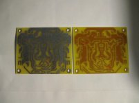

very good PCB artworkFilm flopped or reversed,lettering scrapped off ~
Thanks!

Hi cambe. Very nice.
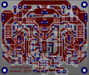
Hi naf. I'm out of home now and will be for the next two weeks, so no ssa for me now. The servo peeceebee artwork is almost ready, but have to do a final checking. I have also prepared a solder mask for clean soldering, a better silkscreen and minor changes from the shown example. Will be uploaded in first week of november. Thanks for your patience.
Btw, pin 3 of opamp goes to ground. Pin 2 and pin 1 are conected to each other only.
A friend here has built 4 pairs of SSA peeceebee. I wanted to grab a pair from him ASAP, but will have to wait two looong weeks now. Pity me.
It's festive season here... Taking a tour to the village where I was born 27 years ago. Right now typing through my cellphone from inside the plane. Yeppiii! Whoooshh...
Hi naf. I'm out of home now and will be for the next two weeks, so no ssa for me now
. The servo peeceebee artwork is almost ready, but have to do a final checking. I have also prepared a solder mask for clean soldering, a better silkscreen and minor changes from the shown example. Will be uploaded in first week of november. Thanks for your patience.Btw, pin 3 of opamp goes to ground. Pin 2 and pin 1 are conected to each other only.
A friend here has built 4 pairs of SSA peeceebee. I wanted to grab a pair from him ASAP, but will have to wait two looong weeks now. Pity me.
It's festive season here... Taking a tour to the village where I was born 27 years ago. Right now typing through my cellphone from inside the plane. Yeppiii! Whoooshh...
Shaan, have a nice trip...Hi cambe. Very nice.
Hi naf. I'm out of home now and will be for the next two weeks, so no ssa for me now
Btw, pin 3 of opamp goes to ground. Pin 2 and pin 1 are conected to each other only.
A friend here has built 4 pairs of SSA peeceebee. I wanted to grab a pair from him ASAP, but will have to wait two looong weeks now. Pity me.
It's festive season here... Taking a tour to the village where I was born 27 years ago. Right now typing through my cellphone from inside the plane. Yeppiii! Whoooshh...
And, may-be it would be good to add two 1nF film caps from OP amp power rails to ground for proper decoupling. TL 072 are quite stable, but some would like to use some other opamp they have as spare parts.i try to draw unused op amp pin like this, any suggest?
Attachments
Last edited:
thank you Sir Esperado,
in my first draw i like to connect pin 3 to ground.
and then i read maxim app-notes in their note is not good to connect pin 3 to ground... here they say
"These two circuits are the most common mistake made when terminating an uncommitted op amp. They are equally bad because the op amp's output will be railed low, causing the op amp to consume more supply current."
and here the link Avoiding Noise and Power Problems with Unused Op Amps - Application Note - Maxim
Hi, naf.
"If the circuit has dual supplies, ±3V for example, the two resistors are not necessary and simply grounding the non-inverting terminal is sufficient."
The non inverting pin will be at 0V, and because Gain factor= 1 the out, then the inverting pin will be at the same potential. No problem.
And some opamp does not like their input to be at the rail potential, as the can invert their output in that situation.
Last edited:
Hi, naf.
"If the circuit has dual supplies, ±3V for example, the two resistors are not necessary and simply grounding the non-inverting terminal is sufficient."
The non inverting pin will be at 0V, and because Gain factor= 1 the out, then the inverting pin will be at the same potential. No problem.
And some opamp does not like their input to be at the rail potential, as the can invert their output in that situation.
Thank you very much for your explanation Sir.
Actually i did search howto proper termination of unused opamp pin after reading your alert to Shaan SSA Servo.

Chrisophe,
I was only thinking of the possibility, but the transducers (speakers) are operated at DC pulses at the sample rate of 44.1kHz. There is no analog involved it is purely digital. The transducers need be quite small and light and a very fast, but I am sure this is possible. A Guy like MiiB would need to say if he can make such a transducer.
As you say 2 speakers would give you +6 dB more than 1 speaker; 16 speakers moving forward would give you +96 dB higher SPL and 24 speakers moving forward would give +144 dB higher SPL.
This follows the digital value faithfully. Besides there should be no distortion either and of course no feedback, it is a a pure digital system and will generate very little heat and whatever the supply could deliver would be passed to the transducers.
I don't said that. It is true only if the acoustic wave length is large enough that you can consider distance between speakers as 0. So this is true only at low frequencies. I said the average level increase is 3dB, doubling loudspeakers. Very well known by PA managers :-(As you say 2 speakers would give you +6 dB more than 1 speaker
In a way, logical: it double the power, not the level.
I don't know who said this but they are wrong................As you say 2 speakers would give you +6 dB more than 1 speaker; 16 speakers moving forward would give you +96 dB higher SPL and 24 speakers moving forward would give +144 dB higher SPL. ............
If one speaker with One unit of power gives a relative output level of +0dB,
then 2speakers with 2units of power get to +6dB
4spkr & 4p get to +12dB
8spkr & 8p get to +18dB
16spkr & 16p get to +24dB, NOT +96dB.
If the group of 16speakers were fed with the same One unit of power, then the relative output level would be +12dB.
But, as usual with an array of speakers, one must consider over what frequency range that extra sensitivity is available.
I don't said that. It is true only if the acoustic wave length is large enough that you can consider distance between speakers as 0. So this is true only at low frequencies. I said the average level increase is 3dB, doubling loudspeakers. Very well known by PA managers :-(
In a way, logical: it double the power, not the level.
Not true, each speaker would undergo a cone movement that would be equivalent to say the supply of 5V dc being applied to the transducer for one period of 22uS. I think this is worth investigating if someone already has please tell me.
I was only thinking of the possibility, but the transducers (speakers) are operated at DC pulses at the sample rate of 44.1kHz. There is no analog involved it is purely digital. The transducers need be quite small and light and a very fast, but I am sure this is possible. A Guy like MiiB would need to say if he can make such a transducer.
Noooo.... transducer technology is light years away from that. Unless low-fi is acceptable then yes it is possible even today
Did-you forget the inertia of the cone ?Not true, each speaker would undergo a cone movement that would be equivalent to say the supply of 5V dc being applied to the transducer for one period of 22uS. I think this is worth investigating if someone already has please tell me.
And remember, if you send a high level 22µs pulse in-it, you will get awfull cone fractioning effects (distortion, etc...).
More than that, if you change the emitting surface at each level step, you will change the dynamic response curve a very strange way.
Last edited:
But i think, Nico, that your idea can take some sens if we imagine some compression driver adding 16 motors (bits) in one horn. Because source will stay concentric and same emitting surface whatever the level. And 6db gain here, yes, if the units are at the same distance from the throat.
- Status
- This old topic is closed. If you want to reopen this topic, contact a moderator using the "Report Post" button.
- Home
- Amplifiers
- Solid State
- Simple Symetrical Amplifier