dear Shaan, if you want to just print and iron, i think this is the correct one.
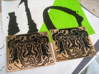
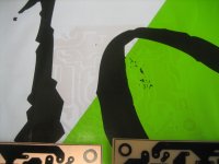
left is your new corrected 10k resistor, right is my first board
left is your new corrected 10k resistor, right is my first board
Attachments

Last edited:
after all you're fast ShaanThe good one. Promise. Print and Iron.
I am apparently a rookie after all.
Thanks Naf.


now i just donwload it, print and iron...no need manual edit anymore Thank you.
Last edited:
Thanks Sheldon,Here's my all BJT version: http://www.diyaudio.com/forums/solid-state/193923-simple-symetrical-amplifier-272.html#post3081421
A couple of points: I'm using Thermaltrak outputs. You can substitute standard power BJT's and an ordinary VAS multiplier. You'd still want the NTC to compensate the front end (thermally coupled to the input pair).
Distortion will rise above a certain power level for this simple version, as the VAS will be loaded at higher output levels. I don't need much power, and I haven't seen any issue. For more power you can use the output design from the all BJT SST thread.
Sheldon
I will see
that, but maybe I don't have enough skill if there something to modifyand I already order the lateral pair...(thanks to Naf for the info)
Now I'm waiting for my own thinking which one will be build
It is really hot thread he...3x
Regards
glad to hear dear John, no it's up to you to choose your poisonThanks Sheldon,
I will see
and I already order the lateral pair...(thanks to Naf for the info)
Now I'm waiting for my own thinking which one will be build
It is really hot thread he...3x
Regards
Good luck.
hi LC..." SSA Low Impedance HP " is a great progress from SSA i think.Hi guys
Finally, I am proud to announce that the SSA Low Impedance HP design project is prepared. It was a DIY community mutual project since there are ideas, knowledge, effort and of course time & energy of many involved, to offer free SSA amplifier project to all interested.
Happy DIY, enjoy, regards Andrej
P.S. Special thanks to Alex, you're the Man.
any plane " SSA Low Impedance HP " for PA (kw)?
dear sir,
how can i set bias voltage at gate of mosfet.
thanks
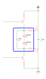
Like the attachment for autobias.
Or a 1K Trimpot replacing the diodes for manual bias setting.
Only for Laterals.
Attachments
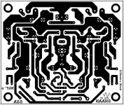
It seems, the text on Shaan's first PCB lay-out confuses others.
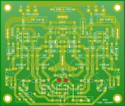
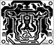
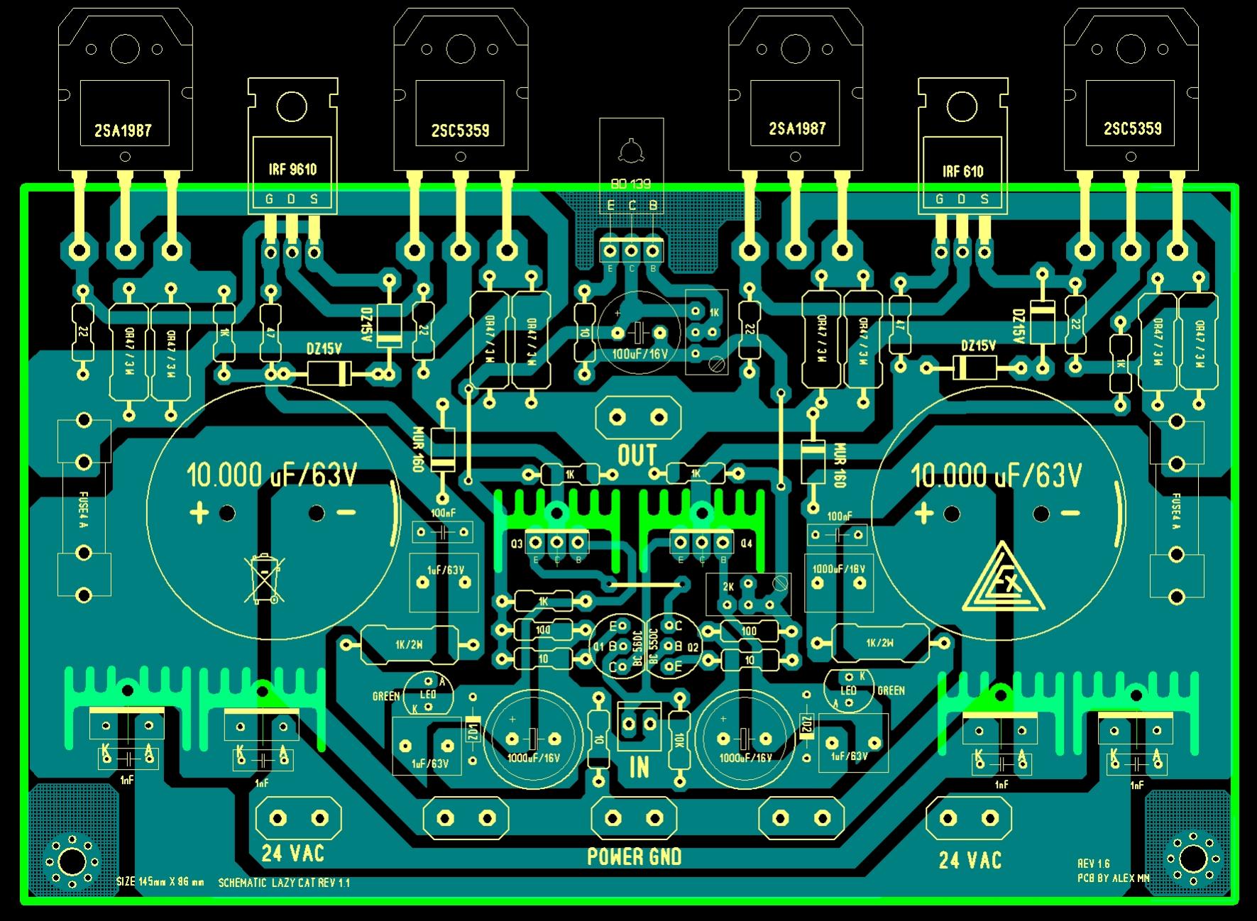
The corrected PCB with the readable text (left image) and Naf's posted corrected PCB with the reversed text (right image) are both correct for toner transfer. No need to mirror. See the components lay-out (center image), the imaginary copper tracks and both the b&w bottom copper tracks matches. Personally I don't mind the text but I look into a particular spot in the pcb artwork, and in Shaan's design the input. The input in the component lay-out goes to the right side and in both the b&w bottom copper (for toner transfer) the input was also on the right side, then that is good to go for toner transfer. Of course after the image has transferred to the pcb it will become reversed but then you will be flipping the board so that the parts sits on top of the board and not on the bottom copper exactly just like on the given component lay-out..
The corrected PCB with the readable text (left image) and Naf's posted corrected PCB with the reversed text (right image) are both correct for toner transfer. No need to mirror. See the components lay-out (center image), the imaginary copper tracks and both the b&w bottom copper tracks matches. Personally I don't mind the text but I look into a particular spot in the pcb artwork, and in Shaan's design the input. The input in the component lay-out goes to the right side and in both the b&w bottom copper (for toner transfer) the input was also on the right side, then that is good to go for toner transfer. Of course after the image has transferred to the pcb it will become reversed but then you will be flipping the board so that the parts sits on top of the board and not on the bottom copper exactly just like on the given component lay-out..
Attachments

you've got it!, i'm always print it in paper and see throgh the light before toner transferring...and that's why i manually flip SHAAN and SSA text.It seems, the text on Shaan's first PCB lay-out confuses others.
The corrected PCB with the readable text (left image) and Naf's posted corrected PCB with the reversed text (right image) are both correct for toner transfer. No need to mirror. See the components lay-out (center image), the imaginary copper tracks and both the b&w bottom copper tracks matches. Personally I don't mind the text but I look into a particular spot in the pcb artwork, and in Shaan's design the input. The input in the component lay-out goes to the right side and in both the b&w bottom copper (for toner transfer) the input was also on the right side, then that is good to go for toner transfer. Of course after the image has transferred to the pcb it will become reversed but then you will be flipping the board so that the parts sits on top of the board and not on the bottom copper exactly just like on the given component lay-out..
Perfect DIY...well almost...
Hi abetir,
What paper did you use to transfer the toner in the pcb?
Regards,
Boyet


..pretty close Shaan..
It's actually an A4 copy paper wrap.
boyet,
I was told the A4 size stickers being sold at National Bookstore is ideal for use on toner transfer method (you won't be needing the sticker of course just take the "backing paper"), better yet check on the "Staples" brand. I dunno' if you can find the "wrapper" that I've used, it was actually for office use, but I guess any glossy type paper that can tolerate heat without peeling off, should be good enough for the job.
In laserjet toner transfer method, "practice makes perfect"
Yihaaa.... nicely done ...perfect DIY
Thanks Naf!
I just hope I can populate the board the soonest...right now i'm feeling real slow working on my other amp build.
Dear Lazy Cat ,
can you suggest what to change in schematics to adapt it to 40-45VDC regulated PSU or even 56VDC if not regulated (didnt decided yet)?
http://www.diyaudio.com/forums/atta...-symetrical-amplifier-ssa-bigbt-basic-pcb.jpg
And output transistors.I have MJL21194/15025 but theese are too slow i guess,only 4mhz. I have NJL3281 too which is 30mhz device but it's with diodes ,different pinout.But that's managable if needed.
- Status
- This old topic is closed. If you want to reopen this topic, contact a moderator using the "Report Post" button.
- Home
- Amplifiers
- Solid State
- Simple Symetrical Amplifier