Easy way to know a Mosfet is lateral is when pin order is g s d. Verticals are g d s.
Shaan a friend has made your version P2P. Just without the input cascode base trimmers, DC input, still steady he says. He used an IR led and small trimmer instead of your 2 biasing diodes between drivers in the end, so to can match the channels output bias and take it to 200mA. 25mA through drivers and 5mA through input BJTs he tells me over the phone. He is not as happy yet as with the one we had battled with early in thread for some aspects of sound, although much easier to be DC stable over the bridge. He will add our JFET CCS from the older amp idea for first stage to compare. When I will meet him and examine I will tell you more.
I see. Then the sound without a CCS is not up to his liking. Perfectly possible. He made P2P? Nice. Well, without the diodes for biasing it's not totally the one I used though. The sound it produced(producing) have a clean and transparent character. But then again, maybe it's just me who likes it the way it is. I wish him all the best with the jFET CCS.

")
The bias stability I think is the characteristics of Shaan's SSA circuit. But for sound quality I'm afraid the 2 biasing zeners are also the determinant factor.
Hi jay. Yes the diodes may have some influence over the perceived sound character. I am not very knowledgeable about it and haven't tried is with trimmer or resistor for biasing so I can't comment on it.
I guess that Shaan biased the input stage more than 5mA, but at least 10mA, most probably 12mA (I don't know if Shaan has mentioned about this).
The input pair has a current of less than 3.5mA and the VAS has 15mA through them. I mentioned all these in one of my posts after page 272.
The previous Nico's circuit focuses on THD hence biases the front end with lower current. One important characteristics I found with Nico's circuit was that, with certain setting, the 2nd order distortion can be very dominant, giving a very lifelike sound.
If you are talking about how the simulated Fourier graph looks then I found the opposite to be true in my config; odds dominant and very low even order, second harmonic less than third. I have installed degeneration in VAS which Nico didn't use. Maybe this has some effect on second harmonic being dominant.
In real listening test I didn't have a hint of that second harmonic character in the sound. But yes it is very life-like and far from "sweet" "fat" etc and at high volume none of the program material sounds masked/compressed, meaning very low THD at high output levels, but how much low... I don't know.
Sound of diodes ???Yes the diodes may have some influence over the perceived sound character. I am not very knowledgeable about it and haven't tried is with trimmer or resistor for biasing so I can't comment on it..
Whatever components, they are not perfect. (Diodes vary their voltage dropout depending currents, zeners are noisy, transistors gain vary with instant temp of their junction, Current sources does not have infinite impedance etc etc.). So they introduce distortions, both static and dynamic you can measure.Diodes, leds, resistors may have different resistance, and of course for the diodes, a function of current. We want certain bias current but also certain voltage across the gates. So, imo it is not just about to get the right current, but also voltage.
And reduce in improving each part in order they do their job as near as dreamed (expected
.But i do not understand this reference with some "sound characteristic" of any element, like if it was a cooking ingredient with some kind of smell or taste. Electrons have no musical preferences or affinity Components have characteristic, and a condenser can have opposite effect depending where it is used... as everybody knows.
I see. Then the sound without a CCS is not up to his liking. Perfectly possible. He made P2P? Nice. Well, without the diodes for biasing it's not totally the one I used though. The sound it produced(producing) have a clean and transparent character. But then again, maybe it's just me who likes it the way it is. I wish him all the best with the jFET CCS.
Shaan that is a fresh build, its only some news over the phone. I will see and listen at a point. Has to solidify in build details yet. 200mA is his per rail total, 170mA his output stage. It just gives 40dB OLG, 33kHz OL-3dB and 13dB FB if you close the loop in LT SPICE, maybe he misses some damping, who knows. What current you draw in your 1K2 resistor CCS on your amp? Just tell me the voltage drop over those. Is it in 12.5 to 15mA ballpark? That will help to choose JFETs and to see how near those amps are between them.
I'm searching where is the all BJT version of this SSA, dont find it yet
So please help
Here's my all BJT version: http://www.diyaudio.com/forums/solid-state/193923-simple-symetrical-amplifier-272.html#post3081421
A couple of points: I'm using Thermaltrak outputs. You can substitute standard power BJT's and an ordinary VAS multiplier. You'd still want the NTC to compensate the front end (thermally coupled to the input pair).
Distortion will rise above a certain power level for this simple version, as the VAS will be loaded at higher output levels. I don't need much power, and I haven't seen any issue. For more power you can use the output design from the all BJT SST thread.
Sheldon
Shaan that is a fresh build, its only some news over the phone. I will see and listen at a point. Has to solidify in build details yet. 200mA is his per rail total, 170mA his output stage. It just gives 40dB OLG, 33kHz OL-3dB and 13dB FB if you close the loop in LT SPICE, maybe he misses some damping, who knows. What current you draw in your 1K2 resistor CCS on your amp? Just tell me the voltage drop over those. Is it in 12.5 to 15mA ballpark? That will help to choose JFETs and to see how near those amps are between them.
The current in the 1K2 resistor is indeed 12.5mA.
Still you bypass the diodes with an electrolytic for AC in your amp. What goes on if you snub that cap with 0.33R 1uF MKP?
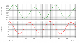
I used the cap to bypass the diodes for the AC currents in the VAS (see attachment, green trace is current variation in diodes, red trace is AC current through cap, 8uA through diodes vs 60uA through cap!).
Now, why I did this? Coz its common practice, and makes sense.
Attachments
Last edited:
Yes. However, this current controls the VAS current through the input BJTs, if I'm not wrong.
VAS current may be different if there are different or no degeneration and different device gain, the resistor current still being 12.5mA.
...And has the heavy influence that detracts from the diodes, and you can play with bypass quality...
Yes, the cap I placed their was chosen from the best I found soundwise. And I have experience with some good looking expensive electros making an otherwise good amp sounding like puke!
Yes. However, this current controls the VAS current through the input BJTs, if I'm not wrong.
VAS current may be different if there are different or no degeneration and different device gain, the resistor current still being 12.5mA.
Driver can up or down its current by trimming your 220R cascode load that sits between B,E. 1K2's CCS (resistive) current carries the feedback resistors feed also.
Yes, the cap I placed their was chosen from the best I found soundwise. And I have experience with some good looking expensive electros making an otherwise good amp sounding like puke!
Was it an orange one if I remember well? Looks like German make, or something different?
Driver can up or down its current by trimming your 220R cascode load that sits between B,E. 1K2's CCS (resistive) current carries the feedback resistors feed also.
Yes. But I was particularly talking in respect to the resistor current only. There may be many more ways to change the current through the VAS, like increasing the PS voltage.
Was it an orange one if I remember well? Looks like German make, or something different?
It's a Keltron 100uF/40V. Indian make, orange.
- Status
- This old topic is closed. If you want to reopen this topic, contact a moderator using the "Report Post" button.
- Home
- Amplifiers
- Solid State
- Simple Symetrical Amplifier