I like your Cap multiplier, but it has one drawback, fixed output voltage. Why not alowe that the output voltage follows slow changes of the input voltage like common Capacitance multiplier.
I am using a kind of a cap multiplier in my amp. It contains over current and loudspeaker DC protection. If someone does not like the current limiting it can be removed.
dado
Are LL and LR the speaker inputs? Does DC at the output shut down the regulated supply or ?
No offence Mr Mikelm, I was not directly pointing to your Efforts but consider it as a general Opinion.Well, I appreciate you have a different opinion, but I don't appreciate your insinuation that my supply is not good and not grounded properly just because you can't be bothered to find out how to design a good choke regulated supply.
I would agree that they, like anything else, have to designed correctly otherwise there can be ringing & over voltage during turn on but just because it is possible to design something badly does not mean that we should not make the effort to design something well.
As esperado Pointed out, Amps are highly dynamic and Power lines have to bear tremendous transient surge with every unit of music it conducts.
Theoretically Amp prefers a zero impedance at power supply .anything more, then there comes a "who is who " situation which is my observation.
Out put transistor fails to understand to whom it is feeding power ,to the loudspeaker in emitter or into choke coil in collector.
At times it is a challenging task to add fuse in the power lines due to above said similar reasons.
Even trivial 78xx regulator suffers from this issue from my experience and only way is proper wiring and decoupling caps closest to the device.
I agree poorly designed chokes worsen the situation I have heard choke coils singing inside amplifier cabinet and that was very silly.
Hi Christophe,
Sorry, I did over react without any explanation so now I will try to explain.
One example of the reason I now always include choke supplies in my designs is this.
I made the twisted pair buffalo DAC KIT which included their "placid shunt regulator" which is a basically a current source element followed by shunt feedback regulation element. Not that dissimilar from Salas's "simplistic shunt regulator"
I think the placid regulator is a well designed and implemented circuit - not necessarily any better or worse than the design that you presented here which I'm also sure is well designed.
These two classic regulator circuits just use a different approached and I'm sure which is preferred will just down to individual preference.
However, the similarity with these designs is that the earth line is continuous from transformer secondaries ( or post diode ) all the way to the final circuit. You may think that this is not significant, but based on my experience, I think it is very significant.
I built the dac in this normal industry standard way and enjoyed the rich smooth sound.
However, when I then inserted CLC choke regulation upstream of these regulators in ALL the supply lines including the earth supply line - similar to the schematic above - the sound of the DAC was transformed - It really came to life & sounded much better.
I know you don't believe that this kind of filtering can be any better than the kind scheme you presented but I have tried it both ways and noticed a clear and obvious improvement with the chokes present.
I think if you consider it carefully you will see that there is good logic for including series impedance in the earth lines as well as the voltage lines.
If you try it, I think you will like it")
cheers
mike
Sorry, I did over react without any explanation so now I will try to explain.
One example of the reason I now always include choke supplies in my designs is this.
I made the twisted pair buffalo DAC KIT which included their "placid shunt regulator" which is a basically a current source element followed by shunt feedback regulation element. Not that dissimilar from Salas's "simplistic shunt regulator"
I think the placid regulator is a well designed and implemented circuit - not necessarily any better or worse than the design that you presented here which I'm also sure is well designed.
These two classic regulator circuits just use a different approached and I'm sure which is preferred will just down to individual preference.
However, the similarity with these designs is that the earth line is continuous from transformer secondaries ( or post diode ) all the way to the final circuit. You may think that this is not significant, but based on my experience, I think it is very significant.
I built the dac in this normal industry standard way and enjoyed the rich smooth sound.
However, when I then inserted CLC choke regulation upstream of these regulators in ALL the supply lines including the earth supply line - similar to the schematic above - the sound of the DAC was transformed - It really came to life & sounded much better.
I know you don't believe that this kind of filtering can be any better than the kind scheme you presented but I have tried it both ways and noticed a clear and obvious improvement with the chokes present.
I think if you consider it carefully you will see that there is good logic for including series impedance in the earth lines as well as the voltage lines.
If you try it, I think you will like it
cheers
mike
Are LL and LR the speaker inputs? Does DC at the output shut down the regulated supply or ?
Yes and yes.
Yes and yes.
Thank you. Very nice. But this would be useful only when the output stage itself does not put out any DC or show imbalance when unbiased from the front end.
What if one of the rails of the output stage fails? Most circuits will show the full rail voltage of the polarity intact.
Or is this a circuit to power up the whole amp including the output stage?
No offence Mr Mikelm, I was not directly pointing to your Efforts but consider it as a general Opinion.
Thanks for your response jayadev,
I should put my design in context then I think it may make more sense.
Because I like the sound of quite efficient speakers and also because I don't like going to bed with my ears ringing my personal amplifier power requirement are really quite modest.
I have noticed on the scope that the typical voltage output when I'm listening is usually about 3V peak rarely reaches 5V peak.
For this kind of power consumption I find that 22,000uF - 30,000uF / channel is quite sufficient even if there is high impedance between these caps and the transformers at high frequencies.
My modest requirement gives me the freedom to focus almost entirely on the quality of the supply rather than the raw power ability.
Also I would not necessarily recommend this supply for a chip amp where not further filtration is possible for the i/p & VAS stages.
So what I'm saying is, this supply works very well on the kind of amplifier and speakers that I use it with and I accept that it may not be suitable for all tastes & systems.
cheers
mike
What would-be the benefit ? Is it safer to the amp power transistors to see a fixed voltage, If you remove the zener from my regulated supply, you'll get a cap multiplier. But Zener help to filter too.I like your Cap multiplier, but it has one drawback, fixed output voltage. Why not alowe that the output voltage follows slow changes of the input voltage like common Capacitance multiplier.
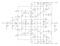
There is no active current protection, because i wanted less impedance as possible in the PSU source. Because my protection is sensing at the output of the amp.
Only a slow start system to take care of the caps, minimize the collector to emitter voltage of the PSU power transistors during start-up, protect the fuse, preventing everything, including your home outlets, from the terrific inrush current of a > 1000W PSU with big amount of capacitance.
Just a single big resistance, in serial with the trasfo (primary side), shunted 5sec after power-on. Value of this resistance (R1) is calculated to allow the voltage to be 95% of the nominal one at quiescent current of the amps.
http://www.esperado.fr/images/stories/protection-totale-definitive.gif
What i wanted to point out is this kind of stabilized PSU can be better (on a musical point of view) than a regulated one where you sense the rails voltages. Because in the last case, you introduce a loop with delays and create often some overshoots on the rails during transients recovery. After all, a regulated PSU is just an amp, with a good PSSR, amplifying a fixed voltage witch need to be at least as fast as the musical amplifier itself. Not really easy. Can be done, but much more complicated and expensive.
What i wanted to point out is the benefit of such a simple stabilization, compared to a single passive circuit, is obvious on the musical point of view, that you can compare instant, shorten collector/emitter of the psu transistor if your amp can afford the collector voltage.
Great musical benefits, minor investments.
Last edited:
Wilson Mirror. Good? Bad?
Hi LC and others.
The precision zeners and jFETs are out of my reach but still want to use a CCS as current feeder, with as low parts count as possible.
I tried the simple mirror in the sim. It's pathetic. But the Wilson seems excellent both in mirroring and +/- current balance, almost totally dependent on the value of the 1K ground resistor. Plus current variation during signal at input is extremely low(in the nano-amperes range); suggesting very high impedance current output. It also uses the same BJTs as the inputs/cascodes. Do others have experience with this CCS here? If so, then please share and help. Expert's opinion welcome.
Thanks in advance.
Planned schema attached.
Attachments
Thank you. Very nice. But this would be useful only when the output stage itself does not put out any DC or show imbalance when unbiased from the front end.
What if one of the rails of the output stage fails? Most circuits will show the full rail voltage of the polarity intact.
Or is this a circuit to power up the whole amp including the output stage?
It will not detects small DC output offset and if one of the rails of the output fails it will shut down other one immediately.
This regulator powers whole amp, imput stage has additional c multipliers on the amp board.
dado
What would-be the benefit ? Is it safer to the amp power transistors to see a fixed voltage, If you remove the zener from my regulated supply, you'll get a cap multiplier. But Zener help to filter too.
There is no active current protection, because i wanted less impedance as possible in the PSU source. Because my protection is sensing at the output of the amp.
Only a slow start system to take care of the caps, minimize the collector to emitter voltage of the PSU power transistors during start-up, protect the fuse, preventing everything, including your home outlets, from the terrific inrush current of a > 1000W PSU with big amount of capacitance.
Just a single big resistance, in serial with the trasfo (primary side), shunted 5sec after power-on. Value of this resistance (R1) is calculated to allow the voltage to be 95% of the nominal one at quiescent current of the amps.
http://www.esperado.fr/images/stories/protection-totale-definitive.gif
What i wanted to point out is this kind of stabilized PSU can be better (on a musical point of view) than a regulated one where you sense the rails voltages. Because in the last case, you introduce a loop with delays and create often some overshoots on the rails during transients recovery. After all, a regulated PSU is just an amp, with a good PSSR, amplifying a fixed voltage witch need to be at least as fast as the musical amplifier itself. Not really easy. Can be done, but much more complicated and expensive.
What i wanted to point out is the benefit of such a simple stabilization, compared to a single passive circuit, is obvious on the musical point of view, that you can compare instant, shorten collector/emitter of the psu transistor if your amp can afford the collector voltage.
Great musical benefits, minor investments.
First if you use fixed output voltage you need more voltage drop on the regulating transistor to compensate for the mains varation. More voltage drop means less for the amplifier and more lost power in the regulator. By the way zener will generate more noise.
My regulator has a current limiter but with variable dalayed trigger, more current, faster reaction. It starts at, let say, 10 A with reaction of hundreds miliseconds and at 30 A is a few miliseconds.
If you don't like current limitation(limited with fuses only) and GNFB used in the regulator, then look here.http://www.diyaudio.com/forums/solid-state/216780-tt-amp-200w-8ohm-701w-2ohm-6.html#post3124702
C multipliers are on the same amp PCB no current limitation, standard C multiplier with no GNFB and a loudspeaker protection included.
dado
Hi Shaan
Wilson current mirrors as CCS nicely fit in SSA sch instead of current injection resistors. Signal distortions and AC performance in whole will be improved significantly. The only potential issue I see here is thermal stability of injected currents, so careful BJT matching and thermal coupling must be done. Two cascode BJT-s have to be located away from Wilson pairs, since cascodes dissipate most of the CCS power and having different thermal conditions as coupled pairs. I suggest you to assemble one Wilson current source/sink separately and test its current stability while heating its parts with suitable heat source (solder iron). This will give you an impression of how the circuit will fit/behave inside SSA sch and to pre-eliminate later surprises.
Wilson current mirrors as CCS nicely fit in SSA sch instead of current injection resistors. Signal distortions and AC performance in whole will be improved significantly. The only potential issue I see here is thermal stability of injected currents, so careful BJT matching and thermal coupling must be done. Two cascode BJT-s have to be located away from Wilson pairs, since cascodes dissipate most of the CCS power and having different thermal conditions as coupled pairs. I suggest you to assemble one Wilson current source/sink separately and test its current stability while heating its parts with suitable heat source (solder iron). This will give you an impression of how the circuit will fit/behave inside SSA sch and to pre-eliminate later surprises.
Fishing for compliments, Shaan ? ;-)CSS with as low parts count as possible.
As far as i know, there is no better Accuracy/Simplicity ratio than Wilson Current mirror.
The only issue is it deteriorate with high frequency.
And temp variation effects, as pointed by L.C, but symmetrical on both rails.
Dado: Agree with all, Just a remark, with high voltages (>60V) 6v of drop just represent 10% of loss eq <1db.
Agree too with the keep-it-simple Zener noise : will try a low noise current source to see if any listening impact. If i worry about rail noise in preamps and converters, i use to neglect this aspect in main PSU for power amps. May-be i'm wrong ?
To LC, it would be interesting (i will do on my side if i find time for that) to study a perfect PSU for the SSA. I imagine a combination of serial and shunt regulation, ( with big loss of power expected ;-). Something like common serial and one shunt regulation on each amp board. To see if any noticeable sound improvement.
At this level of quality, no major improvement can be done amp side. PSU can bring the next big step. Don't you think ?
It will not detects small DC output offset and if one of the rails of the output fails it will shut down other one immediately.
This regulator powers whole amp, imput stage has additional c multipliers on the amp board.
dado
Thought as much that this regulated supply must be for the whole amp. Can we expect each rung to supply about 10Amps. Ideally how much capacitance should precede and succeed the regulator?
Hi LC.
Thanks for the points. I'll assemble the mirror tomorrow on the existing board replacing the resistors(seems it will be easy).
Hi Esperado.
Please understand this, you are over-estimating me; I learnt about the Wilson mirror just yesterday, from Wikipedia. I thought I would ask the kind guys here, diyaudio, as I have neither any experience with it nor do I have an electronics degree. To my naked eyes the Wilson seemed the best mirror with lowest parts count. I simulated it to verify. Do you not like all this? Then I'm sorry I disappointed you and wasted your time. But please either quote the full sentence when you reply or try avoiding use of poverbs in your posts. My mother language is Bengali, not English. Thanks.
Oh, please, Shaan, it was a smiley of sympathy !!!But please either quote the full sentence when you reply or try avoiding use of poverbs in your posts.
You asked for a simple and good current source design and propose in the same message the best possible response.
Then, "the fishing for compliment" was just a second degree wink to say "indeed".
English is not my English language neither and i try my best.
Sorry for my bad sens of humor.
I don't know how experienced you are in electronic, and, if as you says you are an electronic beginner, you deserve hundred time more everybody's (and my) respect.
You work with passion, in a creative way, and i love people which experience by themselves, try various solutions instead of simply copy other's work, and are not afraid to take risk. You certainly not make loose time to nobody here. Please, keep on truckin, i'm sure you will be soon an amazing audio designer.
Last edited:
Thought as much that this regulated supply must be for the whole amp. Can we expect each rung to supply about 10Amps. Ideally how much capacitance should precede and succeed the regulator?
I use 4700uF + 10000uF per rail with 0.11R between and that was quite enough. This preceed the regulator, and succeed anly what is on the amp PCB, in may case 470uF per rail plus additional c multipliers for input stage.
dado
You asked for a simple and good current source design and propose in the same message the best possible response. Then, "the fishing for compliment" was just a second degree wink to say "indeed".
I see, got it. Sorry for the misunderstanding. Apologies.
I have simulated the temperature co-eff of the Wilson mirror. And must admit that it really has a big dependence on the device temp, drifting the offset as high as 400mV. This is when the +ve mirror is hot and the -ve is not.
But, when I heat both cascodes of the mirror to say 70 degrees(and hotter) then the offset only drifts about 25mV or so. It seems the offset is affected when the cascodes are at different temperatures, like the input pair.
Is it safe to thermally couple just the two + and - cascodes of the mirror, as well as the mirror pairs of each polarity?
Thanks.
Last edited:
But, when I heat both cascodes of the mirror to say 70 degrees(and hotter) then the offset only drifts about 25mV or so. It seems the offset is affected when the cascodes are at different temperatures, like the input pair.
As I said in #2931
Two cascode BJT-s have to be located away from Wilson pairs, since cascodes dissipate most of the CCS power and having different thermal conditions as coupled pairs.
Is it safe to thermally couple just the two + and - cascodes of the mirror, as well as the mirror pairs of each polarity?
Thanks.
You did it correctly, just right like it is in the picture.

- Status
- This old topic is closed. If you want to reopen this topic, contact a moderator using the "Report Post" button.
- Home
- Amplifiers
- Solid State
- Simple Symetrical Amplifier