Not to spoil the shutting down of the feedback discussion completely, but to state how I see things...I may be completely of track...but this makes sense to a mechanical guy...
Feed back compares levels...A real time scale lock...Trouble is that it comparing slightly time shifted levels...and with increasing frequency this time shift matters more and more and hence the distortion increases with frequency...makes perfect sense to me...feedback is not comparing wave-forms, it's comparing levels.
Feed back compares levels...A real time scale lock...Trouble is that it comparing slightly time shifted levels...and with increasing frequency this time shift matters more and more and hence the distortion increases with frequency...makes perfect sense to me...feedback is not comparing wave-forms, it's comparing levels.
Not to spoil the shutting down of the feedback discussion completely, but to state how I see things...I may be completely of track...but this makes sense to a mechanical guy...
Feed back compares levels...A real time scale lock...Trouble is that it comparing slightly time shifted levels...and with increasing frequency this time shift matters more and more and hence the distortion increases with frequency...makes perfect sense to me...feedback is not comparing wave-forms, it's comparing levels.
Fully agree when you replace time shifted by phase shifted
")
jan
Hi Sonnya,
At the moment I can't show you recent work yet*, but if you like, have a look at some outdated stuff from the past: here and here.
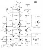
* At the moment I'm busy with translating a MicroCap file to FreePCB (PADS format) and after that, drawing the PCB itself. A hell of job and expensive too (to get an impression see the thumbnail of the schematic below).
As you see, it's the opposite of a Simple Symmetrical Amplifier.
edit: It's like a V8 engine with two desmodromic valves per cylinder.
Cheers,
E.
Or a pushpull driver for every mosfet. Your front end is vfb where i am more to cfb but complexity is the same in My cfb design with an modificede current mirror.
Go for orcad. In Denmark they have a lease plan. Then you Can combine pspice with sch and pcb. Or the more expensive dxdesigner with hyperlynx and pads interactive router
"pour les couilles du pape"
Aaaaaaargh! Am I talking here "pour les couilles du pape"*?
If you are talking about a time shifted signal (inside a feedback loop), thus without amplitude roll-off at higher frequency, such system is unstable (by definition). If, under marginal conditions, it might happen to be stable, then it does not increase the distortion.
True.
Anyhow, you folks make me really angry, as you refuse to understand or accept that time shift is NOT the same as phase shift.
* In Dutch: "Voor de kat zijn kut".
[...]
Feed back compares levels...A real time scale lock...Trouble is that it comparing slightly time shifted levels...and with increasing frequency this time shift matters more and more and hence the distortion increases with frequency...
Aaaaaaargh! Am I talking here "pour les couilles du pape"*?
If you are talking about a time shifted signal (inside a feedback loop), thus without amplitude roll-off at higher frequency, such system is unstable (by definition). If, under marginal conditions, it might happen to be stable, then it does not increase the distortion.
makes perfect sense to me...feedback is not comparing wave-forms, it's comparing levels.
True.
Anyhow, you folks make me really angry, as you refuse to understand or accept that time shift is NOT the same as phase shift.
* In Dutch: "Voor de kat zijn kut".
Anyhow, you folks make me really angry, as you refuse to understand or accept that time shift is NOT the same as phase shift.
* In Dutch: "Voor de kat zijn kut".
You are right,
Time shift description makes the feedback limitation much more easily understandible...
Phase shift issues in feedback are much more complicated to explain as they are also time shift but are also frequency depandent and involve additional compexity..
Or a pushpull driver for every mosfet.
Right. BTW, the bunch of extra trannies cost me virtual nothing.
Your front end is vfb where i am more to cfb but complexity is the same in My cfb design with an modificede current mirror.
If you need the ultimate speed, admitted, go for cfb. But in my case I finally opted for the lowest possible distortion (THD-20k of the front-end is ca. 50 ppb) and lower offset.
Go for orcad. In Denmark they have a lease plan. Then you Can combine pspice with sch and pcb. Or the more expensive dxdesigner with hyperlynx and pads interactive router
Orcad? No way (I have used it once). I stick with MC, the most user friendly, versatile and fastest simulator you can get (it's written by real programmers, thus it's not bloat ware). The only drawback is that it is not integrated with a PCB package, though it does a translation to different PCB packages. But in most cases you have to (re-) define (or assign) the shapes and pins of the components (in conformance to names of the target S/W).
You are right,
Time shift description makes the feedback limitation much more easily understandible...
Phase shift issues in feedback are much more complicated to explain as they are also time shift but are also frequency depandent and involve additional compexity..
No! It's just the other way around. I repeat, on top of that, without amplitude roll-of a NFB system is by definition unstable.
Sure it's unstable... If for we eases shake hold the delay or time shift through the devices constant, then the phase-shift increases with frequency..when that phase-shift reaches 180 degrees the feedback becomes additive instead of subtractive and it would thus make the amplifier unstable. It would go into wild oscillation. This is in return prevented by introducing frequency limitations, so the gain is less than 1 at 180 degrees. Off-course by introducing level compensation we add another pole and thus introduce additional phase issues making the understanding a little more complex.. as the level is not only time-shifted from the components in the signal path, but also by the level filter components that with increasing frequency also adds an increasing phase-shift.
Last edited:
time is phase...or..??
If you look at it in the time domain, one can speculate that phase change can be represented by a delay in time over a single cycle, over a series of cycles phase delay and time has no significance at all.
If we "mix" two identical wave forms (like we do in negative feed-back and the input stimulus) the vector result of the phase change is a constant amplitude directly proportional to the phase angle between the two wave forms.
For instance if the phase angle is zero the constant component will be zero, as the phase angle progresses through 90 the constant would be a maximum and as it shifts though to 180 degrees it decreases again to zero.
If the phase angle between the two signals were varying continually a resultant signal will be developed as described by the Doppler effect.
Pure negative feed back does not contribute to any form of distortion at all.
Last edited:
You are right,
Time shift description makes the feedback limitation much more easily understandible...
Phase shift issues in feedback are much more complicated to explain as they are also time shift but are also frequency depandent and involve additional compexity..
No no no! Phase shift is NOT time shift!
Are we surrounded by morons here??
Did anybody read this: http://www.diyaudio.com/forums/solid-state/193923-simple-symetrical-amplifier-259.html#post3074321
If you don't agree with that, why not, pray tell?
If, otoh you Don't Get It, stop regugitating nonsense!
jan
Last edited:
No no no! Phase shift is NOT time shift!
Are we surrounded by morons here??
How would you make signal time shift in 100% analogue circuit? Explanation please.
Simple, compare a direct stimulus with the same stimulus that has passed through 10 km roll of cable there will be propagation delay (time delay).How would you make signal time shift in 100% analogue circuit? Explanation please.
Last edited:
No no no! Phase shift is NOT time shift!
jan
In absolute terms it`s not the same ... I agree.
Phase shift @ a constant frequency produces a certine time shift or a delay in time.. if you call it that.
A 30 dergree shift in 1khz can be measured in time, it`s always delayed, it never appears before of the input signal...
A 1mhz 30 degree of shift would represent a much smaller time shift/delay.
So the element of time / shift / delay is always present here even though that shift / delay is frequency dependent.
And that does not mean that I claim you to be wrong.
There's a delay line in almost all analog scopes. Google is your friend.
jan
... and this analog delay circuit is what, 10 km long transfer link or simple LC circuit?
Fixed frequency signal phase shift with attached circuit is time delayed or what?
Attachments
A very high order lowpass can look a lot like a time delay. I have often wondered about this. Cables AFAIK at their frequency limits have a very steep rolloff (or is this just an artefact of simulated cable models?). So it does not surprise me to draw a connection between high order behavior and time delay. As far as the feedback loop is concerned, they have similar effects. It is as simple as: at any frequency where a positive input signal causes a greater positive feedback signal, there will be oscillation.
The difference is that, theoretically, phase shift can be restored by compensation, but time delay cannot. However, with very high-order phase shifts, the distinction may become moot, because in the real world only so much compensation is possible.
Is this reasonable?
Even if there is phase shift, there is no time delay. What you see may look like it, but no. Even the phase shifted signal responds immediately to input, just the high frequencies are attenuated so perceptually it is different. If you are in the habit of seeing all signals as a collection of sine waves, you may not understand this because the sine wave is a very theoretical concept. Think about it. We interpret phase based on where the crest is. Is this a sane way to look at it at all times though? After all a lowpass does not move the crest by shifting all spectral components back in time - it simply responds to the integral of the sine wave (or whatever the opposite of derivative is). So I think sticking to the high school description of a sine wave will cause confusion because it compromises accuracy in return for practicality.
- Status
- This old topic is closed. If you want to reopen this topic, contact a moderator using the "Report Post" button.
- Home
- Amplifiers
- Solid State
- Simple Symetrical Amplifier