Originally Posted by PauloPT
Can anyone please look at my simulation files on post #2011 and tell me what I'm doing wrong? Thank you.
R6
The problem is if I increase R6 I get huge distortion. 300 Ohms gives me (only) about 1%...

Thank you.
Will do. But might be a couple of weeks before I can get to it.
Gave it (CCS under top driver) a quick try with LSK170. Shows some promise. I had overshoot before, but clean rise and fall now on square waves. Some HF noise, but no time to track that down. The 170 is not ideal, because current doesn't level out until about 10V G/S. Need better part, or wait a see what LC's fix is.
Sheldon
With K30ATM and BF245A had tested only. But mine's LAT and low driver bias suffices. Check if your input BJTs still run about the same Ie, and if the amp's output tracks sine wave well symmetrically when cranking it up on the scope. Say at 30V pk-pk. About HF noise, see if its acting up so to revisit comp caps or input filtering 'cause the CCS boosts its speed. Will some NTC find enough temp to react when bundled with two small BJTs running 30mW each? We must get to know which exact type works for LC first. Still the CCS is fixing the drivers bias stability not the input drift. But in a bridge everything interacts non the less.
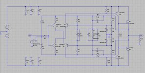
Try R6,8,11,12=510 Ohm
Also R13,16,23=375 Ohm for ~3mA bias in the drivers and ~100mA in the Lats.
So for 180mA bias what would be the value of this resistors?
Forgive my poor knowledge of electronics design, I'm reading Sedra & Smith - Microelectronic Circuits - for learning but I'm still very in the begining.
Run .op and manipulate R23 until you will get what you need through the LATs. In reality R23 better be a trimmer. The simulator won't have exactly the same Vbe for the drivers or Vgs for the LATs as each one ranging practical part. Just make Nico's as given but with trimmer R23, trimmer R6 and see if it will bias up and work stable on you. You gotta get hands on to experience how it moves... In mysterious ways that is.
With Nico's values for the resistors distortion is huge. The sugested above values work like a charm! Why did Nico used the values that give worst distortion?Just make Nico's as given but with trimmer R23, trimmer R6 and see if it will bias up and work stable on you.
Only laterals. What Nico showed are real values biasing real parts. Those which worked best in LT Spice are biasing models. Shows how sensitive it is non the less, because those values I gave for the good sim aren't really far. You got to see when hands on and use trimmers on crucial ones until you set it right as I said. Those are just my general opinions trying to help out though, I am not Nico and maybe the right answers are different, remember. In general this is a practical thing. You make it, you evaluate bias and stability on your layout, you try for good offset. You gotta have generator and scope absolutely. Not recommended as novice's project. If in doubt, get official boards and make F5, next of kin best thing. Just my plan B suggestion if things go wrong, not trying to disappoint you.
You're not disappointing me, I thank you for your advice.not trying to disappoint you.
This is an interesting thread. I'll be following it and when a final stable design is achieved I'll build it.
Thanks.
Hi PaulPT,
There is no absolute GO/NO-GO condition in analogue electronics and tweaking practically is more often than not the final stage of the design. Besides, I think that DIY audio guys (myself included) places far too much emphasis on harmonic plots from simulators.
It is possible to optimise every component using a simulator and get really silly numbers. Problem is one eventually believes that it will be the actual performance of the product - it never is.
I am still using my lazy cat to this day, everyday in my office. Even with the assumed high level of simulated distortion, its sound remains absolutely magic.
- Status
- This old topic is closed. If you want to reopen this topic, contact a moderator using the "Report Post" button.
- Home
- Amplifiers
- Solid State
- Simple Symetrical Amplifier