And what is your feeling about Mosfets ?
Hi Christophe, I think you are the best one to explain the relationship between physics or theory and what is heard or perceived. I just like to relate what I hear with theory. But it doesn’t mean that I understand it.
So far I like mosfets best. Actually tube is better, as it’s high end (frequency) is unbeatable by even the best bipolar or mosfet amps that I know of. But to get it’s low-end comparable to bipolar or mosfet speed, it takes a lot of dollars.
Tube is very good in one area (especially due to linearity) and bipolar is good in another area (mostly due to trans-conductance). What we want is the best of both worlds (or a good blend of it based on individual preference and setup) with limited budget. Imo, mosfet has the most suitable characteristics for this job.
Also note that for cost-no-object amplifier I still prefer tube amplification. So for limited budget, tubes are still doable in line level. The low current requirement and the non-existence of output transformer make this possible. And because mosfet works better with tubes than bipolar, this makes the mosfet even more (slightly) preferable than bipolar.
Imo, almost 100% of amplifying device perceived sound is a product of its measurable characteristics. Designers only try to make use of these different characteristics. For mosfets, the most important ones imo are ciss and gm. Ciss affects linearity and thus high frequency performance, and gm affects output impedance and thus its ability to synergy with (most) speakers (and low-end performance indirectly).
In my mosfet implementation, I prefer to use high gm mosfets in source follower, and low ciss mosfets (including laterals) in drain follower (but laterals works fine in both).
NP used IRF244 in Alephs, and IRF240/9240 in FirstWatts. I used IRFZ34/IRF9Z34. It is a smaller mosfet (requires careful cooling) but better in both gm and ciss. Because I don’t like the sound of JFET in general implementation, I used an inversed Aleph where the output is IRF9Z34 (P-channel) and the input is 2SK1336 mosfet (N-channel). So both stages has better ciss mosfets (in drain follower) than the original Aleph.
For SE source follower, I used IRFP150 (have only 4 of them) and IRFP250 when paralleled device is required. I have higher-gm mosfets, but size are small and the ciss is very high. These mosfets in SE do not have high enough gm to drive most speakers.
For class-B, VFET rarely work because of the high Ciss needs some special treatments. Stochino amp is the last amp that I have built where VFET is used in class-B. In class-B (where global feedback is an evil), mosfet sound is “dirty” due to the high ciss. But look at the bass quality due to its trans-conductance (and wide bandwidth design). Ime (with my speakers), symmetrical complementary VFET (in class-B) has shown the best bass performance, and is probably very suitable for bass amp in an active 3-way system. This is an example where the bass performance is the best of the both worlds of tube’s “fuller” bass and bipolar’s “fast” bass.
For class-B mosfet, I will stick with the SSA with laterals. And I hate it that so far only MiiB has designed with a high voltage rail (60V). Imo, the laterals need high supply rail (60-70V) to sound at its best. But I’ll wait…
About JFETs, may-be the problem do not come from them, but the way they are used ?
Of course I believe so. I think (or guess?) after the small current amplification with JFET, it should be followed by another stage so gradually up until higher current/voltage amplification. A small bipolar stage after the JFET might help. After all, what we hear is actually a system of amplifiers and speaker, not just a JFET alone.
is this "liveness" just less distortion or some small signal losses ? Or their different noise factor's curve ?
May be the analogy is like an opamp in DAC I/V stage. The higher the slew rate of the opamp, the higher the input (voltage) error. That’s why precision op amps have “bad” slew rate. And guess what, “we” prefer the sound of the highest slew rate opamp here, not the most precision one.
Hello, Jay
Your amp building experience is wide and rises definite respect. At the same time, I can not agree with attributing resulting sound to a kind of active parts - tubes, mosfets, etc.
jFETs can result in amplification stages sounding better than tubes - one shoud choose those of them with few pF Ciss, rather than 100pF like for 2SJ74.
Another point, I have found out that observing of definite schematics DESIGN PRINCIPLES are much more important than to select between BJT or MOSFETs. With tube designs, choke input PS and high quality caps usually is a must, while typical PS at SS designs do violate one important design principle, what makes useless any competition with tubes at trebles domain.
With my gratest respect to Lazy Cat and excellent measured performance of the SSA designs, I am not active in this thread because of impossibility to implement my empirically found design principles.
If one uses standard PS and Push-Pull output stage at SS design, irrespective of the rest of schematics and measured parameters, one must forget about competition with good SE Tube amps at mids and highs. With other design principles one can repeatedly win against best tube designs.
Last edited:
You know Vladimir I veru nearly agree with you......
YOUR experience definitely arouses my respect!
If you want it to sound like a tube, use a tube, a quote stolen from NP but as true today as it was in the eighties. But mosfets in SE are pretty damn good, too, especially with the very clever power supplies you use.
Hugh
YOUR experience definitely arouses my respect!
If you want it to sound like a tube, use a tube, a quote stolen from NP but as true today as it was in the eighties. But mosfets in SE are pretty damn good, too, especially with the very clever power supplies you use.
Hugh
If you want it to sound like a tube, use a tube, a quote stolen from NP but as true today as it was in the eighties. But mosfets in SE are pretty damn good, too, especially with the very clever power supplies you use.
Hugh
Hello, Hugh
I would attach to NP setnence, that " a King is made by persons surrounding him". By varying surrounding parts and design solutions, one could approach any definite tube design as close as one likes (at mids and highs), or even overcome it. A "king" in "a person" of 1pF jFET or 1pF tube will be able to affect only very very little the result of the "surroundings".
Last edited:
Lazy and modder got 1 day bin yesterday night for calling each other a certain name. Lazy was first, modder described him as top of that name list as a reply. That is breaking rule 1 by both parties. Comments on that mod action are pulled on rule 12. No more comments please, nobody is using insulting names on nobody no matter what, is the policy. 
Hello, Jay
Your amp building experience is wide and rises definite respect. At the same time, I can not agree with attributing resulting sound to a kind of active parts - tubes, mosfets, etc.
jFETs can result in amplification stages sounding better than tubes - one shoud choose those of them with few pF Ciss, rather than 100pF like for 2SJ74.
Another point, I have found out that observing of definite schematics DESIGN PRINCIPLES are much more important than to select between BJT or MOSFETs. With tube designs, choke input PS and high quality caps usually is a must, while typical PS at SS designs do violate one important design principle, what makes useless any competition with tubes at trebles domain.
With my gratest respect to Lazy Cat and excellent measured performance of the SSA designs, I am not active in this thread because of impossibility to implement my empirically found design principles.
If one uses standard PS and Push-Pull output stage at SS design, irrespective of the rest of schematics and measured parameters, one must forget about competition with good SE Tube amps at mids and highs. With other design principles one can repeatedly win against best tube designs.
Hello Vladimirk ,
Could you elaborate more on input choke PSU ...... !!!
Lazy and modder got 1 day bin yesterday night for calling each other a certain name. Lazy was first, modder described him as top of that name list as a reply. That is breaking rule 1 by both parties. Comments on that mod action are pulled on rule 12. No more comments please, nobody is using insulting names on nobody no matter what, is the policy.
Imagine both in the same room .....
")
Hello Vladimirk ,
Could you elaborate more on input choke PSU ...... !!!
This discussion will be off topic, so in very few words, for achieving top level, one must be very careful with parts quality, mechanical vibrations, and electromagnetic coupling between various device components. These issues have nothing to do with simulated THD and IMD.
With traditional PS and output stages at SS designs, think what is going on during time perion when diodes of rectification bridge are opened, output signal modulates all currents passing through PS wiring, their radiation is enough to affect badly sensitive parts at amp PCB. Input choke PS helps a bit, but even better would be shunt like PS.
One of the best SS amps from Technical Brain (Japan) has unusual input place for power cable, and it is clear to me why it is so.
Last edited:
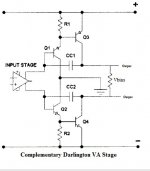
VAS arrangement ?
I'm thinking is it possible to integrate this VAS to SSA ? I think it is known as complementary darlington VAS.
It seems have good properties, but I have no idea what value should be CC1, CC2, R1 & R2. Is possible to use without those capacitor ?
I'm thinking is it possible to integrate this VAS to SSA ? I think it is known as complementary darlington VAS.
It seems have good properties, but I have no idea what value should be CC1, CC2, R1 & R2. Is possible to use without those capacitor ?
Attachments
Andrej ---> We Are With You !!! No Mather How Many Storms may Come !!!
DearVery efficiently spent time recently, regarding business and hobby
Some jerks will never learn their lesson, morons up to their ends.

Andrej,
I Just Wonder To Speak Here For All The Good Will, Good Diy Spiritual Members,
Who Simply Admire Yours Great Heart - Soul - Unselfish Will . . . and Give . . .
To All Of Us Positive Sound Lovers . . . .
I truly Wish You A lot of Good Business Spirit
and Even More Nice & JoyFul Hobby Time
and Most of All,
I wish You As Much As Possible Tastefully Sound Listening Moments,
With Yours Soul & Spirit Inspired Designs, For Which Most Of Us We Are
Truly Thankful To Yours Genius Gifts Giving to the All
Audio CommunityWorld-Wide

A. G.

Thanks Smiley and all of you guys
appreciate a lot. Andrej,
Release the Kraken!!!
Fredlock
I did
 back from the battle


LC,
The order of my VAS transistor has arrived, 2SA1707/2SC.
http://docs-asia.electrocomponents.com/webdocs/1002/0900766b810021b5.pdf
having 150Mhz response, high Hfe, seems suitable to as VAS.
What should I improve in my circuit other than having a driver and better VAS ?
(which transistor should i use as driver ? is MJE13032/33/34/35 enough or use MJL3201 better ? or other recommendation ?)
Given that have sufficient improvement, what value should i put on feedback resistor ?
Hi Guitar
2SA1707/2SC4487 has only 50 Vce max, so standing alone in the VAS would be possible only at +/-25 V power supply which is rather low for the purpose, otherwise you have to use them with cascodes.
The most suitable stand alone VAS transistor is 2SA1209/2SC2911 from Sanyo.
Last edited:
I'm thinking is it possible to integrate this VAS to SSA ? I think it is known as complementary darlington VAS.
It seems have good properties, but I have no idea what value should be CC1, CC2, R1 & R2. Is possible to use without those capacitor ?
If you don't want to use cascoded VAS this is also very good solution for high current gain "single" VAS device regarding input stage isolation from output load impedance influence.
Omitting CC1, CC2 would be unwise-impossible cause amp without them would certainly oscillate. Their values depends on many factors but it would be somewhere in between 20-100pF.
LC, there is a funny thing on my power supply too. Although it is +-40V but it is only 120VA, means for stereo, only 60VA each channel. With load variation from 2ohm - 16ohm, the maximum voltage swing is only +-20V before my trafo gone heaven. (Hope my calculation is correct)
So i guess the 2SA1707/2SC4487 is still suitable for use ? since I have no hope to reach higher....
So i guess the 2SA1707/2SC4487 is still suitable for use ? since I have no hope to reach higher....
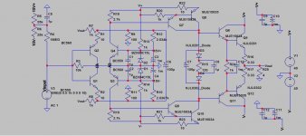
LC, what i'm thinking is such design as attached.
By using those, I get very high open loop gain and low THD.
The VAS are biased as 0.7mA & 10mA
The driver is biased to 1-2mA & 20mA to Output device.
what could be the good number for C13, which is around the OPS, between the Drivers ?
I intend to change those drivers to the 2SA1707/2SC4487 (didn't do in SPICE because no model.....)
and the OPS change from 0281/0302 to NJL4281/4302. (In SPICE, the number is quite outrages......)
Hope it will turn out into a very nice X.x
Attachments
How did we lived before Spice ?Sanyo have poor SPICE library..
which i cannot test before built...
Well, very simple: calculating ;-)
haha.... more than just calculating i guess.... involve experiment to explode, etc etcHow did we lived before Spice ?
Well, very simple: calculating ;-)
Well... I just being more caution X.x afriad to test out physically X.x
Maybe my maths aren't that good for amplifier, need to work up.
Secondary purpose using SPICE is to get those THD values easily. (I don't have those instruments)
Edit : Modern people are too replied on technology......... including me, haha
There is something I dont understand: how can your Q3, Q4 bases be at +15V and -15V while their emitters are at 0V ?LC, what i'm thinking is such design as attached.
[edit] Yes, experimenting in real world and listening seems to me the only way to increase his experience and make-it part of yourself. I'm not sure that all this virtualisation gives no good. It saves time, (money) but kill the soul. (Yes, amps had some kind of soul when they were handcrafted)
Last edited:
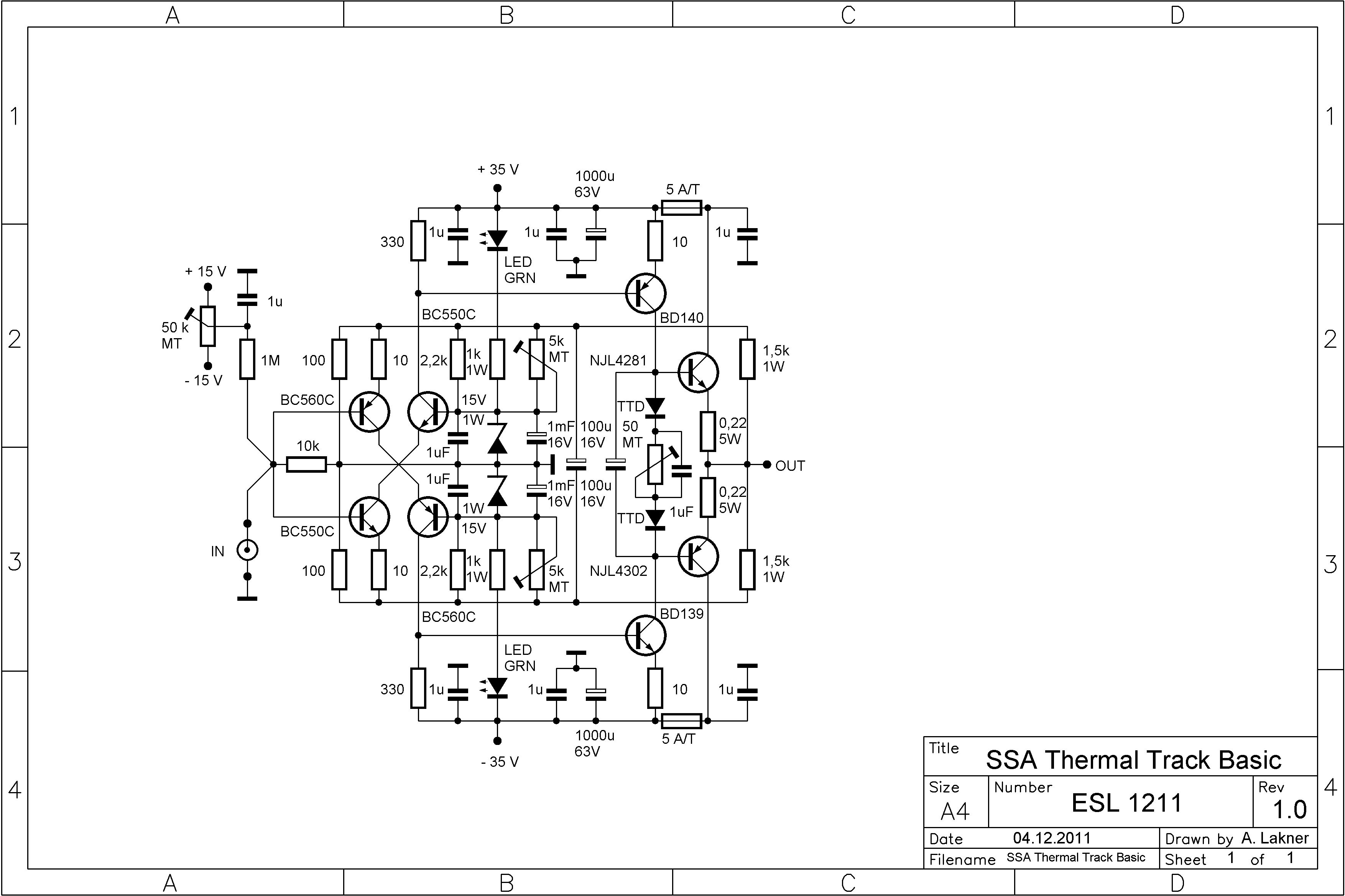
I've got one channel of ThermalTrak Basic built: http://www.diyaudio.com/forums/atta...etrical-amplifier-ssa-thermal-track-basic.jpg
Only significant difference is 2SA1360/2SC3423 for the drivers. Resistor values are as shown, except 2.2R base stoppers for the output devices. Before I fire it up, I could use some guidance on a starting point for the 5K trim pots that parallel the 2.2k resistors into the feedback network. How much current do we want through the zeners, and how much into the feedback network?
Sheldon
- Status
- This old topic is closed. If you want to reopen this topic, contact a moderator using the "Report Post" button.
- Home
- Amplifiers
- Solid State
- Simple Symetrical Amplifier