I challenged anyone over on the fetzilla thread to give one logical reason why 100mV of offset would create any kind of a problem. One person said he thought it gave less detail - apart from that there was not one reason anyone could come up with. Personally, having been living with offset between + / - 70mV these last 6 months I see absolutely no problem and also no loss of detail and I noticed recently that Peter Daniel's DC linked chip amps regularly go up to about 70mV.
You should make objective comparison (reasonable claim).
Not objective --> My Leach amp has offset between +-70mV and it sounds better than my zero offset Sony boombox.
Not objective --> My amp has offset between +-70mV and I see no loss of detail, I can still hear guitar and I can hear violin.
Not objective --> Peter Daniels' chip amp regularly go up to 70mV, so 70mV offset should have no effect.
Objective --> I have built 2 similar mono-blocks. One has zero offset and the other has +-70mV, and I cannot hear any difference between the two amps.
I have never tried the above but my intuition tells me that there is a high probability that I can hear the difference between the 2 amps. Of course the difference can possibly be caused by other than offset reason. But I expect that the one with zero offset will be more trasparent/detailed/hollographic.
Well, you may need to do the above if you want to claim that 100mV offset has no effect. And not forgetting that everyone has different hearing sensitivity.
I challenged anyone over on the fetzilla thread to give one logical reason why 100mV of offset would create any kind of a problem. One person said he thought it gave less detail - apart from that there was not one reason anyone could come up with. Personally, having been living with offset between + / - 70mV these last 6 months I see absolutely no problem and also no loss of detail and I noticed recently that Peter Daniel's DC linked chip amps regularly go up to about 70mV.
Do I expect people to stop fussing about it ? ? . . . well . . . no, it seems that the idea of DC offset is unpopular.
Unless of course you want to connect an o/p transformer for impedance matching - but in a DIY community it might be better to built the amp right in the first place
Well by an idle current of ~500mA, no it is not a problem Mikelm.
But if you idle current is 30 - 50mA, then 100mV into 4 and 8 ohm will be a difference in the output stage posetiv and negative half 12.5mA and 25mA.
Secondly the high bias in the input pair will give a high basis current and it is difficult to match the hfe 100%. So there will be a step in offset if you remove a source like an preamp where you go from a zin of <50ohm to 10 or 20kohm.
I have a amp running here. after removing the DC gain (the DC gain is x1) the offset drift +/-30mV.
When removing the source of 50ohm i have a step of >200mV.
There is a need for adding thermal stability in the smallsignal transistors but also the Zener diodes as they set the bias current in the first stage together with the resistors going to emitter on the input pair.
In comparison my old mirand design has a drift ~5mV with full DC gain with servo removed. The DC offset is +200mV when the servo is removed as i have no DC offset trim added. The Step is 40mV when removing the source with full DC gain.
From this point of view i am not impressed..
But besides from this the amp works and is okay fast....
- Sonny
trying for best safety and stability. Differences are I go for high gain, inevitably less feedback, around 12dB left for it in the Tian method LTSpice analysis with my now drivers. Also controlled the bandwidth to 1MHZ -3dB (measured) for good square waves up to 50kHz without input and output filtering yet (can be needed on real speakers). My goals are never to achieve ''best'' in general but rather ''adequate''. I had even checked 300MHZ Ft Sanyo video transistors for drivers but the amp went too speedy for keeping oscillation trouble at bay. If it will safely and stably outperform the F5 standard in the long run (a rather comparable concept but high bias) in my system (speakers having a 4ish Ohm orchestra power region Z curve) I will be content.
You are too technical. Too "engineer". I think we need a bit of "art" in audio. For example, BD139 may be "adequate" for you. But if for some reason the transistor must withstand less than 700mW, I believe a TO-92 (A970/N5401) will be more "adequate". I myself have prepared to use heatsink for the TO-92.
But that "more oomph" objective is very artistic
What will 100mV at a conventional speaker do ? If it is positive offset it will drive the voice coil of the woofer out of the middle position a bit forward. That position is not well defined anyway in most woofers my many Klippel tests have shown. In a perfectly centered speaker it will increase 2nd harmonic somewhat. If you have luck and the speaker is offset in the direction of the pole piece this 100mV will even cancel 2nd harmonic to a certain degree.
Did anybody measure where it shoots for input and output DC during on/off when the supplies aren't catching up simultaneously for charge and discharge? The more operational offset and drift the more it shoots in my example. Can top 3VDC during off sometimes. Input DC shoots too even up to hundreds of mV.
You are too technical. Too "engineer". I think we need a bit of "art" in audio. For example, BD139 may be "adequate" for you. But if for some reason the transistor must withstand less than 700mW, I believe a TO-92 (A970/N5401) will be more "adequate". I myself have prepared to use heatsink for the TO-92.
But that "more oomph" objective is very artistic
The driver BJT has to swing more than 55VP-P just below nominal power. That means ~40-50mW RMS to be expected when Iq is about 2mA. The drivers when TO-92 can take it after the local CCS trick. Before they blew since with just a resistor their Iq run away hard, frequently. With the CCS the sqw rise time went up significantly also, and the faster TO-92s showed periodic oscillation. Fortune had it that the PHILIPS brand BD pair kept behaving in all areas, with the open possibility of running much more Iq in a future experiment when all other parameters will be fixed. The CCS is good for PSRR there also.
Attachments
Member
Joined 2009
Paid Member
... even tho bipolar sound is not my cup of tea.
do you really believe bipolar has a 'sound' ? I thought that the topology and operating points and power supply are going to have a bigger impact on the sound than choice of FET verses BJT - although I haven't the experience you have, I thought that both of them can be employed to achieve the results you are looking for.
... the SSA is simple and perfect physically.
I have this strange irrational feeling that really good amps are imperfect in some way - technically speaking that is. It's part of the 'Art' as you have said

The SSA has it's weaknesses - thermal stability is one of them - in my opinion, and use of zeners (noisy things). And I think it will sound better if it's NOT actually symmetrical - an easy thing to achieve and I hope to try this out with my TGM5 version.
I would just like to ask, off-set is measured with reference to what? Obviously 0V reference which is dictated by the power supply. If the positive rail caps are slightly more leaky than the negative rail, or if the transformer windings are a few mV difference which is very likely, you are actually offsetting your amp deliberately to compensate for the power supply.
When the signal is applied and the one rail drops in relation to the other, won't there be an immediate dc offset besides the signal. You all talking DC states, you don't listen to DC do you?
When the signal is applied and the one rail drops in relation to the other, won't there be an immediate dc offset besides the signal. You all talking DC states, you don't listen to DC do you?
http://www.diyaudio.com/forums/solid-state/193923-simple-symetrical-amplifier-34.html#post2681206Guys, no worries please, you can always do something like this.
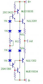
If I have a single output pair for the FC100 buffer, can I do thermal comp. like this? I've left out stoppers and bypass caps for simplicity of display. The 1N diodes are standard small signal diodes, the ones labeled NJL are the Thermatrak diodes.
Attachments
Last edited:
Apassgear,
No disrespect intended, I always get a little concerned by power nuts. It is always a good measure to make the SSA as it was intended, familiarize yourself with it quirks, shortfalls and advantages, and most importantly get a feel for its sound whether it lives up to your expectation before pouring a bucket of transistors into it.
It is relatively easy to expand when you are satisfied that it is the amplifier that you want to live with.
I would just like to ask, off-set is measured with reference to what? Obviously 0V reference which is dictated by the power supply. If the positive rail caps are slightly more leaky than the negative rail, or if the transformer windings are a few mV difference which is very likely, you are actually offsetting your amp deliberately to compensate for the power supply.
When the signal is applied and the one rail drops in relation to the other, won't there be an immediate dc offset besides the signal. You all talking DC states, you don't listen to DC do you?
No problem if the DC values will stay at safe margins in the long run. For the time being this amp can easily give me the creeps some times during on off eratically. Building another channel now to see if its a trend or an error.
Hi Salas
We might be looking for similar results on an amp, I too find the need for some help in the lower region that the F5 can't deliver fully at least with my speakers.
Are you planning to parallel output devices at the end?
Tony
Don't know, got to listen to it critically first when I will have a satisfactory stereo build on hand, hopefully soon.
I have a solution to the drift...
1. You Can use it or not. The 2 input transistor should be feed by an current mirrors feed by a shared currentsource Like cr200..
2. the cr200 Will give an idle current of 2mA +/-10%.. this Will reduce the basiscurrent and remove the heat. The baseresistor for the next stage has to be 5x larger..
This solution is taken from my mirand AMP.
I have a drift starting at 300mV falling to ~50mV. And i Will ADD the circuit above
No problem if the DC values will stay at safe margins in the long run. For the time being this amp can easily give me the creeps some times during on off eratically. Building another channel now to see if its a trend or an error.
Maybe it is a possible error or unsymmetry caused by the fet current source because of its voltage drop ...
Mine SSA BIGBT has no power on thump-pop whatsoever (scope shows 200mV positive jump for the first 0,2 s for no loaded amp) and its thermal DC offset drift inside +/-10 mV over cold to 70°C.
More important issue is an output bias thermal stabilization which can be realized successfully in many ways, already suggested here and in TGM5 thread, how to hold the amp at a certain thermal working conditions.
According to my oppinion the most important feature by this design is its no frequency compensation need as a result of the SSA feedback nature and consequently the sound quality result.
- Status
- This old topic is closed. If you want to reopen this topic, contact a moderator using the "Report Post" button.
- Home
- Amplifiers
- Solid State
- Simple Symetrical Amplifier