Lazy & Fred.
The DUT is passing 100mA and has 4.9Vce when hFE=100.
This is a dissipation of 490mW. The junction will be changing temperature rather quickly.
Need to refine your "method" to help reduce the effect of different Tj on your results.
Hi Andrew ... a lot of Andrews are lurking in this thread

Look I know about the power dissipation in this case but (there's always some but) for a real comparison of power transistors you need to put them near bias collector current (100mA) conditions and compare them in that circumstances. The measurement has to be short one, 2 seconds max, just to read out the voltage value, afterwards voltage on 1 ohm resistor will of course rise up. But the first two seconds are relevant to get realistic comparison. One could even change Vce voltage from 4,9V to lower level with use of a zener in series with 1 ohm resistor but than BJT's Vce/Ic parameters wouldn't be in linear area of the graph any more - out of working point. So proposed measurement is OK, only it has to be performed for a short time.
P.S. This measurement is not about absolute mA (hFE) values but relative ones between output power transistors to find as close matches as possible.
Last edited:
Thank-you. I will try to answer your question on my thread, it looks like this does not interest L.C. at all.Esp,
I like the look and simplicity of your fault detection circuit.
Can you go back to that thread and tell us more on how well it copes with different types of faults, different lengths of transients and at different frequencies?
Hi fredlock
You can use multimeter with hFE function which calculates hFE=Ic/Ib at Ic=1mA.
If you don't have such meter than you can use attached schematic.
Thanks Lazy Cat. I've seen some hFE matching circuit in the internet and also in the forum but just curious what you were using. I was thinking of building this project but I think your simple schematic would be good enough.
Testing hFE at constant Ic is a little more consistent than using constant Ib.
I always use constant Ic now, for hFE measurement even though I don't know Tj.
Multimeters, with a give away for free hFE tester built in, generally use constant Ib.
They are no better than a batching tool. The problem is that one does not know what Ic is.
I always use constant Ic now, for hFE measurement even though I don't know Tj.
Multimeters, with a give away for free hFE tester built in, generally use constant Ib.
They are no better than a batching tool. The problem is that one does not know what Ic is.
Testing hFE at constant Ic is a little more consistent than using constant Ib.
I always use constant Ic now, for hFE measurement even though I don't know Tj.
Multimeters, with a give away for free hFE tester built in, generally use constant Ib.
They are no better than a batching tool. The problem is that one does not know what Ic is.
Could you share us you hFE matching circuit then? Which might benefit me and the others to match it perfectly.
Hi Andrew ... a lot of Andrews are lurking in this thread
Look I know about the power dissipation in this case but (there's always some but) for a real comparison of power transistors you need to put them near bias collector current (100mA) conditions and compare them in that circumstances. The measurement has to be short one, 2 seconds max, just to read out the voltage value, afterwards voltage on 1 ohm resistor will of course rise up. But the first two seconds are relevant to get realistic comparison. One could even change Vce voltage from 4,9V to lower level with use of a zener in series with 1 ohm resistor but than BJT's Vce/Ic parameters wouldn't be in linear area of the graph any more - out of working point. So proposed measurement is OK, only it has to be performed for a short time.
P.S. This measurement is not about absolute mA (hFE) values but relative ones between output power transistors to find as close matches as possible.
Thanks for the explanation LC............
Could you share us you hFE matching circuit then? Which might benefit me and the others to match it perfectly.
+10
Thank-you. I will try to answer your question on my thread, it looks like this does not interest L.C. at all.
Hehe don't worry I looked at yours Crescendo modification to CFB and I must say I'm impressed. I saw you have very small Ic in input pair, is that OK, cause usually input transistors should work at 1-5mA collector current. That also means smaller influence of parasitic capacitances if the collector current is larger, which finally brings you wider bandwidth and higher slew-rate, all though I saw yours sim already shows 380V/us.
Please continue thread in solid state part of the forum I think it will bring more interest from enthusiastic amp builders.
Thanks Lazy Cat. I've seen some hFE matching circuit in the internet and also in the forum but just curious what you were using. I was thinking of building this project but I think your simple schematic would be good enough.
Yes, this circuit test a transistor at constant collector current level you choose with SW combinations, but the same temperature dependency appears here, base current will go down with temperature rising, so matching is again time dependent. For simplicity and relative only comparisons sake I suggest you to built simpler one.
Last edited:
Testing hFE at constant Ic is a little more consistent than using constant Ib.
I always use constant Ic now, for hFE measurement even though I don't know Tj.
Multimeters, with a give away for free hFE tester built in, generally use constant Ib.
They are no better than a batching tool. The problem is that one does not know what Ic is.
Multimeters usually have fixed Ic to 1mA, but that is usually not accurate enough for comparison between power transistors.
hFE measurement at Ic=100mA is just a fine compromise between accuracy and power dissipation vs. temperature dependency.
At mine proposed NPN/PNP measuring schematic no formula calculations are necessary, mV reading is actually hFE data.
Dear Mr. Andrej
Thank You very much for the most beautiful SSA-V12 version.
You make me the beautiest day since long time awaiting for something to drive my speakers civilized - and You make it.
I know, this is the most Generous Scorpio's gift, You give to the whole worldwide sound-lovers & audio community. Thank You ...
bless You . .
Andreas
Thank you Andreas
I couldn't even think the SSA Balanced V-12 schematic would make you so happy, I'm really glad it did.
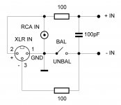
I realize XLR-RCA input connection should also be explained, so here it is.
Attachments
Thank-you, on that mod, I wanted to propose as less modifications of original values as possible. But you are right, will see if any improvement in increasing the current in the input trans, witch was supposed to be 0.2 ma in the original schematic, very good sounding, in fact. A way too to reduce the values of feedback resistances as you like.;-)I saw you have very small Ic in input pair, is that OK, cause usually input transistors should work at 1-5mA collector current. That also means smaller influence of parasitic capacitances if the collector current is larger, which finally brings you wider bandwidth and higher slew-rate, all though I saw yours sim already shows 380V/us.
You only can be impressed by yourself, it is just your idea !
I'm more interested to have your opinion and expert suggestions on my differential protection circuit idea.
http://www.diyaudio.com/forums/digi...sures-class-d-system-project.html#post2731810
If you like-it, i would be very happy to see-it added to you nice SSAs.
I'm working on an integrated solution: Remote power-on of the amp from the 12v preamp rail, soft power with a current limited delay of 2 sec to take care of the power caps and switch on the Loudspeakers after 4 more seconds or so with this "protect against everything" instant reactive circuit.
I will not leave your thread for no price, i just do not want to bore-you with less noise as possible
.As i said, you deserve my sympathy for your passion, generosity and brilliant expertise, makes-me remember when i was young, so many years ago ;-)
Yes, this circuit test a transistor at constant collector current level you choose with SW combinations, but the same temperature dependency appears here, base current will go down with temperature rising, so matching is again time dependent. For simplicity and relative only comparisons sake I suggest you to built simpler one.
Thanks LC for your straight forward answer and brilliant advise. Appreciate it.
Elegant as always . . .
Thank You Andrej for the elegant I/P solution.
Now It is my turn . . . . . . to put Yours genie design into best possible harmony with my ultra low impedance speakers.
My best regards to You,
Andreas
I realize XLR-RCA input connection should also be explained, so here it is.
Thank You Andrej
for the elegant I/P solution. Now It is my turn . . .
. . . to put Yours genie design into best possible harmony with my ultra low impedance speakers. My best regards to You,
Andreas
Some kind of Planar, Orthophase, ot Condenser units ? Ot just paralleled moving coils ones ?with my ultra low impedance speakers.
The most difficult Speakers for all amplifiers on the globe
Esperado,
Apogee Scintilla . . .

Theirs sound is so unique that no conventional speakers come even close.
They require an amp with constant ability drive 0.5 ohm all the time.
Impedance is almost flat line and never leave 0.9 ohm.
The sound, .... incomparable with anything You hear till today - Unique.
They require a nice, civilized arc-welder to drive them, but for return
the listener is constantly in heaven
Regards,
Andreas
Esperado,
Apogee Scintilla . . .
Theirs sound is so unique that no conventional speakers come even close.
They require an amp with constant ability drive 0.5 ohm all the time.
Impedance is almost flat line and never leave 0.9 ohm.
The sound, .... incomparable with anything You hear till today - Unique.
They require a nice, civilized arc-welder to drive them, but for return
the listener is constantly in heaven
Regards,
Andreas
I believed Hifi was dead ! You use ribbons, i use spherical horns, we gone kick the *** of the smartphone's sound ! Did-you tried some good Class D amp for the basses with your crazy speakers ? They love low impedance. Of course, for treble, SSA would sound gorgeous, i presume.but for return the listener is constantly in heaven
Ps: my impedance line is quite flat too, between 5.9 and 6.5 ohms all the way, that's one of the secrets ;-)
Last edited:
- Status
- This old topic is closed. If you want to reopen this topic, contact a moderator using the "Report Post" button.
- Home
- Amplifiers
- Solid State
- Simple Symetrical Amplifier