Basic test result: Iq is very stable. No overheating anywhere. VAS bjts are equally warm.
Offset is NOT. Dancing like balle dancers... seems to have a mind of its own... sometimes +10mV, the next moment -80mV, then -2mV! I can increase the offset from 5mV to say 150mV just by breathing over the input BJTs. I guess the mains AC variations is the main culprit here, as I had the hFE of each input BJT matched before construction. Also I curse the single-turn pot; life is hell with it sitting there. I don't want to use a regulated supply with SSA, so, maybe I'll use my trustful servo with it. We'll see later.
Listening test: I quit LTP. Also, there is more to come(and go) so stay tuned.")
Offset is NOT. Dancing like balle dancers... seems to have a mind of its own... sometimes +10mV, the next moment -80mV, then -2mV! I can increase the offset from 5mV to say 150mV just by breathing over the input BJTs. I guess the mains AC variations is the main culprit here, as I had the hFE of each input BJT matched before construction. Also I curse the single-turn pot; life is hell with it sitting there. I don't want to use a regulated supply with SSA, so, maybe I'll use my trustful servo with it. We'll see later.
Listening test: I quit LTP. Also, there is more to come(and go) so stay tuned.
Last edited:
Quote:
Originally Posted by gannaji
Dear shaan,
Those Heatsinks look nice! Are they available anywhere in India? Can you give me the source in India for the Semiconductors also?
--gannaji
I found them in Kolkata chandni market; the old/used equipment sellers lane, for one-fifth the retail price! These are AMD cpu heatsinks and they can dissipate 100watts with medium air flow. I plan to use them in SSA with a thermo-fan control for the fans.
All the semiconductors used in SSA are available at Nahar Electronics in Chandni market Kolkata. They are very mature suppliers and everydbody knows their shop location, ask anyone in chandni and you'll get there.
Any address or Contact Number of Nahar Electronics? I am operating from Hyderabad. Thank you!
--gannaji
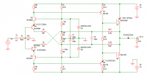
If this is your sch than:
- R1 should be 10 kohm
- R2, R3 should be 100 ohm
- R9 should be multiturn trimer (one fixed value resistor + multiturn trimmer)
- R10, R11 zener supply resistors must have current set to 15-20mA so the zener potential is fixed
- R14 should be coupled with 100 uF
- C1, C2 should be 1000 uF
- D1, D2 also coupled with 0,1 uF
- Q1, Q4 thermally coupled
And your offset will be normal.
So music is already playing hehe
Attachments
Last edited:
People, I'm about to test it right now. Wish me good.
LC, do we need thermal joint between the cascode transistors?
Nice job Shaan - Good Luck
Update: Offset variation is a little better with Iq of 300mA; at the time of last post it was about 170mA. But now I have a little humming in the speaker. Ground loop may be, I'll check.
Shaan, the little humming on the speakers are probably due to the power supply now rippling a little. I had that problem but decoupled the front end with diodes in the power supply, this removed the hum significantly it is barely audible on headphones. My bias is pretty stable after about 10 minutes, but I run the amp in "near class A" at just under an amp.
Nico
It is absolutely normal with an amp flat from DC with no servo. And will have no consequences, as Nico says, as long it is in the 150mv scale, OMHO.Offset is NOT. Dancing like balle dancers... seems to have a mind of its own... sometimes +10mV, the next moment -80mV, then -2mVI don't want to use a regulated supply with SSA, so, maybe I'll use my trustful servo with it.
I highly recommend you use a dynamically filtered power supply (Simple emitter follower, like the one i had suggested in this thread), It improve the sound on transients and noise of all amps as much than the amp itself. Cost a power trans or two and a zener by power line. + additional electrolytic capacitors where huge is never enough ;-)
http://www.diyaudio.com/forums/atta...16209035-simple-symetrical-amplifier-alim.pdf
Replace zener with Tl 431 or so...
Are-you sure there is no very HF oscillation too, hum can be often the sign of it ?But now I have a little humming in the speaker.
Last edited:
Shaan, that verobuild is pure art, underside especially. 
Nico, what is the Iq in the output lateral Mosfets, and is it stable enough, if I will follow your schema with 2SC2240/2SA970 compound driver and 330R R13? Also when you say decoupled the front end with diodes, just those, or an extra cap to ground on the node also? I was thinking of simple capacitance multipliers there even, since the cascode is certainly exposed to ripple.
Nico, what is the Iq in the output lateral Mosfets, and is it stable enough, if I will follow your schema with 2SC2240/2SA970 compound driver and 330R R13? Also when you say decoupled the front end with diodes, just those, or an extra cap to ground on the node also? I was thinking of simple capacitance multipliers there even, since the cascode is certainly exposed to ripple.
Hi Salas, a Capacitive multiplier would do the job even better than my diodes but my PCBs was made a few weeks ago and I opted for the minimum modifications I can get away with. My Iq is about 800mA, yes I run them hot but I find hot is good for two reasons 1) temperature is more stable and 2)harmonic distribution is a nice roll off starting with H2.
Now the amplifier that I compared it with is a single input unbalance current feedback topology, but the balanced version just brought out a few nuances that I did not know existed. Both amps has extended bandwidth, but I think the symetrical complimentary just has that edge better performance in being more transparent. In this topology the artefacts are almost always odd order, but as soon as you over bias you tend to bring out the even order artifacts so that H2 > H3 > H4 > H5.... Although THDis relatively high at 0,2% this does not interfere with a completely transparent performance.
Years ago I used an almost identical topology, it was called Le Gecko, but I over complicated it with current sources and mirrors to the extent that it sounded cynical and not transparent and the reason that I wanted to stick with SSA for its simplistic approach - complicating it diverges from it intrinsic transparent character.
Kindest regards
Nico
Update: Offset variation is a little better with Iq of 300mA; at the time of last post it was about 170mA. But now I have a little humming in the speaker. Ground loop may be, I'll check.
Shaan a ground loop sounds like 100Hz half wave rectified, power supply ripple is a sawtooth in appearance and sounds quite different, it has a sharp tone added in.
Hi Salas, a Capacitive multiplier would do the job even better than my diodes but my PCBs was made a few weeks ago and I opted for the minimum modifications I can get away with. My Iq is about 800mA, yes I run them hot but I find hot is good for two reasons 1) temperature is more stable and 2)harmonic distribution is a nice roll off starting with H2.
Now the amplifier that I compared it with is a single input unbalance current feedback topology, but the balanced version just brought out a few nuances that I did not know existed. Both amps has extended bandwidth, but I think the symetrical complimentary just has that edge better performance in being more transparent. In this topology the artefacts are almost always odd order, but as soon as you over bias you tend to bring out the even order artifacts so that H2 > H3 > H4 > H5.... Although THDis relatively high at 0,2% this does not interfere with a completely transparent performance.
Years ago I used an almost identical topology, it was called Le Gecko, but I over complicated it with current sources and mirrors to the extent that it sounded cynical and not transparent and the reason that I wanted to stick with SSA for its simplistic approach - complicating it diverges from it intrinsic transparent character.
Kindest regards
Nico
Nico, thanks for elaborating. I can appreciate the virtues of a ''simplistic'' approach indeed.
Where would you propose I add a trimmer to the A970/C2240+K1058/J162 schematic we referred to, and in what value for setting not too abruptly between say 0.2A to 1A bias? Since you got to watch the actual amp biasing, you are the best to suggest.Best
Attachments
It is absolutely normal with an amp flat from DC with no servo. And will have no consequences, as Nico says, as long it is in the 150mv scale, OMHO. I highly recommend you use a dynamically filtered power supply (Simple emitter follower, like the one i had suggested in this thread), It improve the sound on transients and noise of all amps as much than the amp itself. Cost a power trans or two and a zener by power line. + additional electrolytic capacitors where huge is never enough ;-)
http://www.diyaudio.com/forums/atta...16209035-simple-symetrical-amplifier-alim.pdf
Replace zener with Tl 431 or so... Are-you sure there is no very HF oscillation too, hum can be often the sign of it ?
Yes I know that this much of offset variation is nothing. But I have read through the thread... the best results has less than +-10mV. I want to achieve that. Maybe I will use the cap-multiplier, but first I have to modify the main circuit a bit, as LC suggests in his last post. There is no VHF oscillation(my radio receivers are alive
and both supply drawing equal current.)Shaan, that verobuild is pure art, underside especially.
Thanks Salas.
Years ago I used an almost identical topology, it was called Le Gecko, but I over complicated it with current sources and mirrors to the extent that it sounded cynical and not transparent and the reason that I wanted to stick with SSA for its simplistic approach - complicating it diverges from it intrinsic transparent character.
Nico, you may take a look at the opamp type SSA I posted on page 78. I built it, in its imperfected state. It sounded FAR from cynical and not transparent, and it is still playing. It has symmetrical mirrors and is running at less than 10mA bias in the output FETs.
Shaan a ground loop sounds like 100Hz half wave rectified, power supply ripple is a sawtooth in appearance and sounds quite different, it has a sharp tone added in.
In my case the hum has audible buzz. It is definitely PS ripple.
If this is your sch than:
- R1 should be 10 kohm
- R2, R3 should be 100 ohm
- R9 should be multiturn trimer (one fixed value resistor + multiturn trimmer)
- R10, R11 zener supply resistors must have current set to 15-20mA so the zener potential is fixed
- R14 should be coupled with 100 uF
- C1, C2 should be 1000 uF
- D1, D2 also coupled with 0,1 uF
- Q1, Q4 thermally coupled
And your offset will be normal.
So music is already playing hehe
Here is what I did:
R1 is 12 Kohm(Don't have 10Kohm in stock)
R2, R3 is still 220ohm. I don't want higher gain and replacing the 2K2 feedback resistors seems to make too much mess, but IF necessary I'll do it later.
No multiturn trimmer available. I use a single turn 2K2ohm trimmer.
Zener supply resistors reduced to 440ohm.
R14 is now with 100uF.
C1, C2 is 1000uF.
Diodes are still alone.
Q1, Q4 eternally kissing each other since the beginning of time.
Offset is totally stable at +-5mV!!!!! Thanks.
BUT
Now I have a LOUDER hum+buzz from the speaker. As if I am using 10uF caps in supply filtering.
Although music is still playing.

Last edited:
Offset is totally stable at +-5mV!!!!! Thanks.
BUT
Now I have a LOUDER hum+buzz from the speaker. As if I am using 10uF caps in supply filtering.
Although music is still playing.
OK nice. Well offset by this amp is auto-cancelled out because of symmetrical design from the input and its DC referenced to the GND only, so normally if everything is done properly there will be only few mV around GND potential.
DC servo is not needed by this design.
Shaan regarding 100Hz hum:
- check the rails ripple filtration, try dual-mono supply arrangement
- rearrange GND connections, you have GND currents interference
- if possible start with only one channel (other off) to cancel hum, than both
I'm sure you will find the way to get rid of hum because at my SSA BIGBT there is only silence at speaker output.
I am from the beginning testing only the right channel.
Ripple filtration is Ok for a class-AB amp. I have used my conventional LTP based class-AB amp with the same supply and same output FETs, it's dead silent with the 15000uF caps.
I'll now isolate the feedback ground from the diode/caps ground. Hope this shows some light.
Hi guys,
Here is my progress report so far:
I built the original SSA BIGBT on a perforated prototype board. The only difference is that a have only one pair of output BJTs, like a "half BIGBT".
I can't say about the sound of this amp yet. You'll see why bellow.
First, the good ... this thing is freaky!!! I measure (it's not simulation) with wave generator and scope and I monitor the input and the output. Output with 8ohm power resistor. With sine wave it's linear from 10Hz (I didn't bother to go lower) to 2MHz, which is the end of my function generator! Added noise seems to be very low, power about 35W/8 ohms, absolutely symmetrical clipping, speed above 100V/us, distortion/spectrum - I don't know.
With square waves is almost scary! I see perfect 10Hz squares, and I've never seen that from an amp for all these years! Squares are almost perfect up to 500kHz, for sure better than most amps would show at 10kHz.
Why I don't listen to it now?! Because it's very unstable. First it's unstable at start-up. The output tends to go close to one of the power supply rails. I even thought I blew it, but then I readjusted the trimmers and all was OK again. So, I wouldn't connect speaker to it for now All that said, have in mind that the input transistors are touching each other and are covered together with RTV silicon for added temperature stability.
Second problem, the adjustments are too sensitive. The DC offset is stable once adjusted but varies with current adjustment. So, you'll have to work both trimmers together.
The other problem with my version is the current adjustment, i.e. the Vbe multiplier. The current is unstable and I saw on several occasions the transistors going slowly in thermal runaway in idle (and, yes, my heatsink is big). On the other hand the circuit is somewhat underbiased. The current may stabilise at say 150mA, but if you run the amp for few minutes with 100Hz sine wave at about 5W of output power, the current will drop and you'll see classic crossover distortions on the output signal. The Vbe multiplier transistor is mounted on top of one of the output BJTs.
So, all in all, it's not ready for use in this form. And I wish very much to finalise it and make it really stable.
Here is my questions:
1. How can I limit the bandwidth to something more normal, like 5-500kHz/3db?
2. How can I make the feedback to work only from 2-3Hz and above, this way expecting more stable DC offset?
3. How can I stabilize the idle current adjustment and make it less "touchy" and less temperature sensitive?
4. How can I safely turn on this thing without readjusting it every time? ... Without DC servo if possible
This amp has great potential. If we manage to make it less dangerous, I suspect it will sound incredibly.
Lazy Cat what's the secret of your prototype? How did you make it stable, aren't you afraid for your speakers?
Regards to all and special thanks to Lazy Cat for the ingenious circuit.
Here is my progress report so far:
I built the original SSA BIGBT on a perforated prototype board. The only difference is that a have only one pair of output BJTs, like a "half BIGBT".
I can't say about the sound of this amp yet. You'll see why bellow.
First, the good ... this thing is freaky!!! I measure (it's not simulation) with wave generator and scope and I monitor the input and the output. Output with 8ohm power resistor. With sine wave it's linear from 10Hz (I didn't bother to go lower) to 2MHz, which is the end of my function generator!
Added noise seems to be very low, power about 35W/8 ohms, absolutely symmetrical clipping, speed above 100V/us, distortion/spectrum - I don't know.With square waves is almost scary! I see perfect 10Hz squares, and I've never seen that from an amp for all these years! Squares are almost perfect up to 500kHz, for sure better than most amps would show at 10kHz.
Why I don't listen to it now?! Because it's very unstable. First it's unstable at start-up. The output tends to go close to one of the power supply rails. I even thought I blew it, but then I readjusted the trimmers and all was OK again. So, I wouldn't connect speaker to it for now
All that said, have in mind that the input transistors are touching each other and are covered together with RTV silicon for added temperature stability. Second problem, the adjustments are too sensitive. The DC offset is stable once adjusted but varies with current adjustment. So, you'll have to work both trimmers together.
The other problem with my version is the current adjustment, i.e. the Vbe multiplier. The current is unstable and I saw on several occasions the transistors going slowly in thermal runaway in idle (and, yes, my heatsink is big). On the other hand the circuit is somewhat underbiased. The current may stabilise at say 150mA, but if you run the amp for few minutes with 100Hz sine wave at about 5W of output power, the current will drop and you'll see classic crossover distortions on the output signal. The Vbe multiplier transistor is mounted on top of one of the output BJTs.
So, all in all, it's not ready for use in this form. And I wish very much to finalise it and make it really stable.
Here is my questions:
1. How can I limit the bandwidth to something more normal, like 5-500kHz/3db?
2. How can I make the feedback to work only from 2-3Hz and above, this way expecting more stable DC offset?
3. How can I stabilize the idle current adjustment and make it less "touchy" and less temperature sensitive?
4. How can I safely turn on this thing without readjusting it every time? ... Without DC servo if possible
This amp has great potential. If we manage to make it less dangerous, I suspect it will sound incredibly.
Lazy Cat what's the secret of your prototype? How did you make it stable, aren't you afraid for your speakers?
Regards to all and special thanks to Lazy Cat for the ingenious circuit.
Please, don't do that. You need 100 X 20 000hz to get a flat phase, so 2Mhz is perfect. Just, limit the bandwidth at the input with a single 6db/oct low pass filter at something like 200Khz, and you'll be sure to never get IM distortion because your amp will be faster than any signal it will have to deal with, and that's the secret of a good sounding piece.1. How can I limit the bandwidth to something more normal, like 5-500kHz/3db?
Comparing tension feedback to SSA curent feedback
Simulating one of my (pretty good) amplifier with a modification according to SSA schematic gives interesting results.
The bandwitch is higher on my tension feedback amp (4Mhz @ -3db) but with a less linear and more rapid slope. 12db/oct for SSA, 18db/oct for Tension feedback. The SSA goes 2MHz @ -3db, and both are the same level @ 10Mhz.
SSA increase the speed from 225V/µs to 250V/µs.
The winner is... SSA !
Attached the two Lt files with models, comparison response curves from 10KHz to 10MHz, and comparison of transients.
Lazy Cat, the values of feedback are far from those indicated by you for my schematic, as the bandwidth, with your low values are something like 1KHz !!!! I had optimized them as you will see on the LTspice files you can play with.
http://www.esperado.fr/SSA/Asymetrical-Input-tension-Feedback1.asc
http://www.esperado.fr/SSA/Asymetrical-Input-Current-Feedback1.asc
Attachments
Last edited:
Nah... SSA is playing music so well that I am having the 'cant-stop-listening-to-prototype-amp' syndrome like Nico.
But, the hum is still there. I think I have some notoriously faulty parts... Or maybe leaky capacitors. I'll do a complete replace of the parts later and update the status!
ps. LC, I have decreased the value of the zener feed resistors in my old opamp-type SSA too. It stabilized the offset variation in that amp too. Thanks again for that tip.
- Status
- This old topic is closed. If you want to reopen this topic, contact a moderator using the "Report Post" button.
- Home
- Amplifiers
- Solid State
- Simple Symetrical Amplifier