The voltage on Vbe multiplier does not change when turning trimmer correction they are 0,3V/0,35V/0,35V
You don't have input collector current. Now it is zero but it should be 4,5mA. Recheck complete input stage, all four input transistors and zener diodes orientation.
")
That won't help at all.
Still, the bias could not be set (in the simulator), and after changing these resistors it could. For as far as I can see, these resistors are parallel to the bias regulator, if the voltage does not rise to the required level (over the bias regulator) I figured that raising the value of these resistors might help (and it did, in the simulator). Probably due to the 10ohm emitter resistors? If I am wrong then please explain why, so I can understand your design better.
Regards,
Frans.
Last edited:
Here is the voltages on the input transistors, but I am no shure are they in written order
As I said, you don't have +/-15 V on zeners referenced to GND. On cathode ZD1 there should be +15V, on anode ZD2 there should be -15V referenced to GND potential. There is your must starting point if these two aren't correct, forget all the other voltage readings.
As I said, you don't have +/-15 V on zeners referenced to GND. On cathode ZD1 there should be +15V, on anode ZD2 there should be -15V referenced to GND potential. There is your must starting point if these two aren't correct, forget all the other voltage readings.
It is not 15V rather measured 14,7V?
It is not 15V rather measured 14,7V?
Look Josip, zener diode is not a voltage reference, its voltage potential is also zener current/production dependent, so across zener diode you should measure something from 14,5V to 15,5V (15V+/-0,5V).
But until you won't have both zener diode potentials correct, it is no use to measure other points potentials as well.
P.S. This is completely basic electronic knowledge, so I am afraid that you will have to look to some books or wikipedia too.
Last edited:
ive seen a few designs on here and i like the look of the one with exicon lateral fets as i have some already, just two questions;
has anyone built and tested it, because i need -3db over 500khz top end and wanted to check?
and, ive seen what looks like and eagle board but as jpeg, does any one have the eagle file i can use as a starting point, i know its cheeky but i have small kids and i dont get much time.
thanks, steve.
has anyone built and tested it, because i need -3db over 500khz top end and wanted to check?
and, ive seen what looks like and eagle board but as jpeg, does any one have the eagle file i can use as a starting point, i know its cheeky but i have small kids and i dont get much time.
thanks, steve.
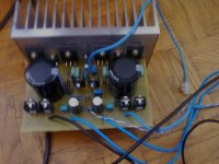
To see I am not fooling you around this is PCB, on witch I have to untie BC550c/560C, and capacitor are 35mm diameter so some components are under the pcb
I believe you, but you have to believe me too for stating this.
I have on ZD1 on cathode 14,83 V on anode 0, on ZD2 on anode 14,55V on cathode 0 so what is the porblem, i am not so clever as you guys?
ZD2 anode should be -15V referenced to GND !!!
sorry it is -14,53VZD2 anode should be -15V referenced to GND !!!
On emitter resistors is 0.4V on BC550C side in BC560C is 0.35V and voltages of input transistors are on picture
again my mistake in prefix -0.4V on bc550c sidebc550/560 are NPN/PNP complementary pair.
They should not show similar +ve voltages.
- Status
- This old topic is closed. If you want to reopen this topic, contact a moderator using the "Report Post" button.
- Home
- Amplifiers
- Solid State
- Simple Symetrical Amplifier