Member
Joined 2009
Paid Member
Hi Hugh,
The trouble is I don't really have space for power supply on-board with 3 channels on one heatsink. I'm not too concerned about it - if I like what I hear I can always scale up to build a no-compromise stereo but for my HT system this isn't warranted. I do like your pcb's though so I'll see if this flat-on-metal approach is feasible.
My version of Eagle doesn't have any blasted library items for a TO-264 package though.
What do you mean by the 'complementary approach' ? (sorry if I'm being thick !)
Member
Joined 2009
Paid Member
doh !Ah, complementary pairs means transistors identically placed but opposite gender supported from positive and negative rails......Hugh
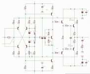
I've started the process of drawing a schematic into Eagle, the general concept is attached. The pcb will be around 75mm x 75mm for each channel. Ignore parts choices, those are just convenient to get the right physical package shape and size - it's the toplogy I need to get right at first.
Output stage is 'standard' AKSA / TGM1 / double EF. Any reason to use something different (all BJT) ?
What am I missing ? do I need to make provision for compensation caps ?
Attachments
Last edited:
It is not a good practice to bypass electrolytic caps with film ones. Not only it do not reduce the impedance in the 10MHz bandwidth, but it increase-it, because the self of the electrolytic (around 15nh) makes a resonant circuit with the film cap. Better to use low ESR (ESL) electrolytics.or use some serial resistance to damp if we want to parallel with films ones.
Last edited:
Gareth,
I can recommend the FetZilla mounting style. It saves space, confers very good cooling, and simultaneously mounts the pcb along with the output devices saving brackets, standoffs, and other messy options. And if you incorporate the power supplies too, you can minimise power supply lead inductance and make it easier to get going.
I couldn't agree more, not only that, I recommend you to do it in that manner. First Alex's PCB was like that.
")
I really like Andrej's complementary approach here, it sims extremely well with almost an evenly descending train of artefacts. My only concern is that you invariably need to set up tight balance between upper and lower halves with consequences for offset control, but aside from that, his approach to avoid AC coupling is inspired and innovative.
Cheers,
Hugh
DC offset is not even an issue in SSA amp, it is in range of +/-10mV no matter what, of course if the input pair is matched and thermally coupled.
This amplifier is capable to operate in VHF band depending on the transistors you choose.
Nico
Linear gain in VHF band, antenna load impedance and still stable as a rock.
Hi Esperado
The praise should go to Lazy Cat, I merely contributed a small portion. I suggested a thread with each design complete with schematics simulation PCB layout and measurements, BOMs, etc. but it never took off.
To be honest my interest in the thread was that the design was just so refreshingly different that I was compelled to add my preferred output devices, the lateral mosfets.
Kindest regards
Nico
Very kind of you Nico. Thank you.
P.S. Some pics pls.
Hi Hugh,
The trouble is I don't really have space for power supply on-board with 3 channels on one heatsink. I'm not too concerned about it - if I like what I hear I can always scale up to build a no-compromise stereo but for my HT system this isn't warranted. I do like your pcb's though so I'll see if this flat-on-metal approach is feasible.
After feeling a taste of the SSA a no-compromise stereo will come too, no doubt about it.
Nico,
I infer that your BJT version is identical to the FET output version, except for the the output devices themselves. Is that correct, or were there other small changes?
Sheldon
Hi Sheldon,
Added Vbe multiplier and the driver transistors changed to BD139/140. I remember I changed the zeners to 5V6, but not absolutely sure, I disassembled it since I settled on the MOSFET version.
Nico
What did-you call a "no-compromise stereo" ? I can understand "no-compromise", (what i called "Not so simple" ?) but what is "stereo". Two amps on the same board (witch i doesn't feel like the best idea ) ?a no-compromise stereo
Apart the Monster from Hirraga, i have not seen any current feed-back amp kit fit power fets (a part a poor bipolar one) available on the market. it would be great.
Last edited:
Member
Joined 2009
Paid Member
Musings on the all BJT options
I've explored a couple of options in the simulator.
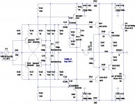
Attached first/left is the same version I posted above for an all-BJT version. [Note that my amplifiers are named TGM1, TGM2 etc. and as this is my 5th amp I'm labelling it TGM5]. It's a simple double EF output with the LazyCat SSA input. Works like a charm in the sims. No turn on bumps either. I take my hat of LC for this simple solution for symmetrical CFB.
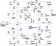
Attached second/right is amodified version, I've taken the cascode devices and flipped them to the output stage. The result is a CFP driver. This design is now effectively a simple symmetric version of my TGM3 amplifier. The high current zener bias stage disappears and instead the feedback node is biassed from the rails (suitably decoupled). Is this still the SSA anymore if I do that so the question is - just because I can, does it mean I should ?
The CFP driver reduces distortion for both versions of the front end.
My simulations show the need for compensation - at the least it requires miller compensation on the VAS. It doesn't need much and the OLG retains an extended region of low phase shift - this thing really is a vhf amp.
Lastly, I noted in my sims that H3 is slightly higher than H2 - contrary to what has been reported for the LatFet output version. I expected a symmetric amp to have more H3. I can only assume, still, that higher H2 comes from device mismatch.
Now, if you look carefully at the 2nd attachment you will see asymmetric emitter degeneration of the input pair. In simulations this provides a nice touch of H2 without any other detrimental impacts.
I've explored a couple of options in the simulator.
Attached first/left is the same version I posted above for an all-BJT version. [Note that my amplifiers are named TGM1, TGM2 etc. and as this is my 5th amp I'm labelling it TGM5]. It's a simple double EF output with the LazyCat SSA input. Works like a charm in the sims. No turn on bumps either. I take my hat of LC for this simple solution for symmetrical CFB.
Attached second/right is amodified version, I've taken the cascode devices and flipped them to the output stage. The result is a CFP driver. This design is now effectively a simple symmetric version of my TGM3 amplifier. The high current zener bias stage disappears and instead the feedback node is biassed from the rails (suitably decoupled). Is this still the SSA anymore if I do that so the question is - just because I can, does it mean I should ?
The CFP driver reduces distortion for both versions of the front end.
My simulations show the need for compensation - at the least it requires miller compensation on the VAS. It doesn't need much and the OLG retains an extended region of low phase shift - this thing really is a vhf amp.
Lastly, I noted in my sims that H3 is slightly higher than H2 - contrary to what has been reported for the LatFet output version. I expected a symmetric amp to have more H3. I can only assume, still, that higher H2 comes from device mismatch.
Now, if you look carefully at the 2nd attachment you will see asymmetric emitter degeneration of the input pair. In simulations this provides a nice touch of H2 without any other detrimental impacts.
Attachments
Hi Sheldon,
Added Vbe multiplier and the driver transistors changed to BD139/140. I remember I changed the zeners to 5V6, but not absolutely sure, I disassembled it since I settled on the MOSFET version.
Nico
Thanks Nico. I think I'll give it a shot with my Thermaltrak extras, and diode string for the thermal comp. Maybe an LED string for the Zeners.
Sheldon
Member
Joined 2009
Paid Member
I've explored a couple of options in the simulator.
Attached second/right is amodified version, I've taken the cascode devices and flipped them to the output stage. The result is a CFP driver. This design is now effectively a simple symmetric version of my TGM3 amplifier. The high current zener bias stage disappears and instead the feedback node is biassed from the rails (suitably decoupled). Is this still the SSA anymore if I do that so the question is - just because I can, does it mean I should ?
Both versions are fine, also simulator confirms that too. Omiting cascodes in second version will certainly impact the sound signature because the input pair dissipate more power also Cbc will influence the freq transition greater than in the first cascoded version. I would also add zeners parallel to C2, C3 in second version. This one has an output buffer with a scale greater current gain than normal so you can expect really nice measuring results too.
Now you can start to built yourself a desirable power amplifier.

I've simmed the LED's before - you need quite a few of them to reach the voltage and PSRR takes quite a hit at the all important 120Hz unless you have separate rails for the front end.
I was thinking of LED's only for Nico's suggestion of 5.6V zeners (3 green LEDs). A single 12V zener, for the front end supply would probably be quieter.
Sheldon
Yes it is one hell of an idea.
Still BIGBT has to be very carefully assembled together with all precautions, hFE matching, ... but at the end it is one hell of a single gain element (see pic). It is fast, reliable and has enourmous energy gain transfer.
P.S. I agree the IRF's are the first on my list to change with some better mosfets in TO-220 case, 2SK216/2SJ79 looks very promising.
Hi Lazy Cat,
You mean to say 2SA1987 and 2SC5359 hFE should be match to be successful in building the SSA BIGBT version? If so, how close they should be matched?
How much bias did you apply on your SSA BIGBT version on post 217?
- Status
- This old topic is closed. If you want to reopen this topic, contact a moderator using the "Report Post" button.
- Home
- Amplifiers
- Solid State
- Simple Symetrical Amplifier