Think this BIGBT is one hell off an idea....when making amplifiers the P and N side are always different....because the devices differ a bit..here You have the P&N included in something that resembles on singe device....
For more current capability you can double the BJT devices and still keep them under a single mossfet control....
I'll do some temp-step simulations with a lateral device (SK216-SJ79) to see how the BIGBT temp-co is...I have a feeling it will be slightly negative...If so I believe they could be the new Black in the amplifier output device world....")
Yes it is one hell of an idea.
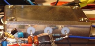
Still BIGBT has to be very carefully assembled together with all precautions, hFE matching, ... but at the end it is one hell of a single gain element (see pic). It is fast, reliable and has enourmous energy gain transfer.
Some features:
- gate current is not unbalancing base currents of NPN/PNP devices
- single drain/source current drives both base currents so both output devices currents are practically the same (50:50)
- you get two collector currents from only one base current, so the current gain doubles automatically just by BIGBT topology (mosfet "feels" like driving only one BJT)
- at quiescent current conditions there are small differences in both base currents because of the Vbe NPN/PNP differences (assuming that current gains are matched), but with higher currents Vbe influence become negligible and base currents are completely the same, consequently also collector currents and both output devices acts like one
In a single BIGBT copper case from the pic there are located 14 discrete elements inside ...
P.S. I agree the IRF's are the first on my list to change with some better mosfets in TO-220 case, 2SK216/2SJ79 looks very promising.
Attachments
Last edited:
Michael, in practice I found this was not quite the case. The amp that you mentioned earlier was Mosfet into BJT (source follower) without Vbe multiplier. The bias on the Mosfets were set high with 2.2ohm source resistor and represented the drive to the speakers to counter cross-over. The bias on the four BJTs had to be set very low at about 5mA if I recall else they thermally ran away.
I am working on this one.
I was talking about one of your earlier post showing a bigger (different) version from that one ..
When you say are they close, do you mean in the next room or are they close in sound?
Unfortunately my system in my listening room consists of eight amps driving eight individual loudspeaker in a multi speaker stereo set-up, so it is not possible really to take the Lazy Cat across and connect it.
The LC is the kind of amp that you cannot take out of the workshop because once you listen to it, you cannot turn it off and it remains on the workbench playing instead of being finished.
The amp has an exceptionally good sound. I am not an audio reviewer but if transparent can be a description then that is what it is. Unlike most projects you tend to listen to the equipment, in this case you tend to listen to the music for a lack of better description.
I do not need to listen loud, the music comes through in a way that it sounds extremely satisfying, but do not make any mistake, even for the "baby" 40 watt amp that this one is, you become pretty anxious whether the speaker is going to survive when pushing it. It just continues to go louder.
If some of you ever listened to a KRELL KSA50, although it is only a 50 watter, it sounds a lot louder than what you expect. Now this amp follows the same reasoning, it gives the impression of playing louder than you would expect.
My Lazy Cat amp is going to stay where it is until such time that I have redesigned a PCB that tips the 100 - 150 watt scale (that is what my requirements are), designed a proper power supply, since I like regulated supplies because it seems to bring out even more detail in an amp.
I will also design an aesthetically pleasing box and have them fabricated into 4 stereo amps because I am old school and like a full rack of equipment looking as impressive as it sounds.
Unfortunately this is not a week-end task and will take a while, but the confidence I have that it will sound absolutely great and become the focus point of my system convinced me that I am prepared to spend a few thousand bucks on them.
That is about all I can say about the design, with the right power supply mechanically sound container taking all the necessary precautions to avoid noises and buzzes and the like, this amp ranks one of the best I have experienced.
Nico
Good stuff Nico, but what version are you listening to .....
The same story happened to me too, I would just listen to SSA and leave it in its web form. It looks like the satisfaction reflex prevents me to perform any changes. It is very interesting pshycological phenomena, but I have to dismantle this spider's web and finally make some serious built out of this schematic.
Thank you Nico for sharing your impressions, appreciate it a lot.
Yes, it does seem like the amp is pretty musical, i want to try one , but it will have to be larger than currently shown as most if not all my current speakers systems require bi-amping and non are above 4 ohms.
I was talking about one of your earlier post showing a bigger (different) version from that one ..
Good stuff Nico, but what version are you listening to .....
Yes, it does seem like the amp is pretty musical, i want to try one , but it will have to be larger than currently shown as most if not all my current speakers systems require bi-amping and non are above 4 ohms.
I know what's on your mind, something like this or even more outputs.
I know what's on your mind, something like this or even more outputs.
Perfecto!!....
 Dats the one , 2 more outputs would work for me ....
Perfecto!!....
... and little more Volts too, I know.

Lazy Cat,
Thanks for sharing this very interesting schematic!
From more practical point of view:
How do you initially adjust the trimmer positions at first power-up? Do you have some sort of procedure?
Isn't there a danger to blow the output transistors if the IRFs are conducting too much and the adjustments are not yet properly set?
You are welcome Ruwe.
Well my track record in BIGBT kill is zero. Two months ago one friend accidentally made full short circuit when connected single speaker cable with 4mm banana from GND to OUT. We heard very loud bang but at the end only one FUSE was replaced. 5% of WBT connector evaporated in the air but all BIGBT's were intact (1xmosfet, 4xNPN, 4xPNP devices, on each rail). The amp has no other current protection than 10A/T fuse.
When you start to power up the unit there are well known current limiting starting procedures (serial rail resistors, bulb lamps, current limited PWS, etc) but always you have to know where is the BIAS trimmer starting position, the schematic gives you an idea, always, and it goes slowly from 0 to let say 100mA per output device. One eye is on scope screen to detect possible oscilation, DC offset, ... it is very straightforward method.
Attachments
Last edited:

When you start to power up the unit there are well known current limiting starting procedures (serial rail resistors, bulb lamps, current limited PWS, etc) but always you have to know where is the BIAS trimmer starting position, the schematic gives you an idea, always, and it goes slowly from 0 to let say 100mA per output device. One eye is on scope screen to detect possible oscilation, DC offset, ... it is very straightforward method.
Thanks,
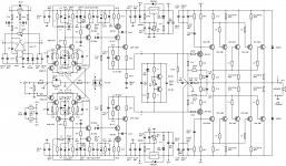
What puzzles me though in your SSA BIGBT Basic circuit is the tempco location. It's not actually directly connected to the gates of the driving IRFs.
I'll change the question
: Is more voltage across the tempco giving more DC current in the output transistors (as usually does in most conventional amps), or it's the other way around?Sorry to bother you again, but I can't understand it clearly in this current feedback circuit.
Hi Ruwe
Currents inside CFB loop are explained here.
If you have SSA Basic version, BIAS is regulated inside CFB loop with a current bypass element like in a simple trimmer form, as a case from the post #1, or with tempco device to track down the bypass current with temperature (in proportion with quiescent current of the output devices). It is not classical Vbe multiplier to change voltage potential but it has to change CFB bypass current.
In more complex SSA version the VAS quiescent current is constant and classical VAS Vbe multiplier or integrated thermal-track diodes are used.
Hi A.Wayne. I have settled on the Lateral MOSFET version. It appeared quite early in the posts and Alex did design a very nice board for it.
Just curious , why lateral Mosfets , Sonics..?
You are welcome Ruwe.
Well my track record in BIGBT kill is zero. Two months ago one friend accidentally made full short circuit when connected single speaker cable with 4mm banana from GND to OUT. We heard very loud bang but at the end only one FUSE was replaced. 5% of WBT connector evaporated in the air but all BIGBT's were intact (1xmosfet, 4xNPN, 4xPNP devices, on each rail). The amp has no other current protection than 10A/T fuse.
When you start to power up the unit there are well known current limiting starting procedures (serial rail resistors, bulb lamps, current limited PWS, etc) but always you have to know where is the BIAS trimmer starting position, the schematic gives you an idea, always, and it goes slowly from 0 to let say 100mA per output device. One eye is on scope screen to detect possible oscilation, DC offset, ... it is very straightforward method.
What schematic is this one LC and it's best when amp is only protected by PSU fuse , well for sonics ...
Hi a.wayne,
Al of my amplifiers of late uses Laterals, they simplify the schematic and they are fast. I have also built the one I described a little later using MJ15001/15002 as output devices, but I could hear no significant difference that would convince me to move away from L-Mosfets.
In fact I do not believe that there would be any significant difference between the IGBT system and mine either. I think that the significance in the apparent clarity and transparency is speed, bandwidth and phase and not harmonic distribution or order. But then that is my subjective observation.
Nico
Thanks for the response Nico, I had given this a look and was curious to hear your thoughts .
http://www.irf.com/technical-info/whitepaper/choosewisely.pdf
http://www.irf.com/technical-info/whitepaper/choosewisely.pdf
Hi Nico Ras!Hi a.wayne,
Al of my amplifiers of late uses Laterals, they simplify the schematic and they are fast. I have also built the one I described a little later using MJ15001/15002 as output devices, but I could hear no significant difference that would convince me to move away from L-Mosfets.
In fact I do not believe that there would be any significant difference between the IGBT system and mine either. I think that the significance in the apparent clarity and transparency is speed, bandwidth and phase and not harmonic distribution or order. But then that is my subjective observation.
Nico
You can give your schemaic amplifier with MJ15001/MJ15002?!
I make that comparison?
Thanks
Hi Nico Ras!
You can give your schemaic amplifier with MJ15001/MJ15002?!
I make that comparison?
Thanks
I used the schematic of Lazy Cat in # 183. Used MJE340/350 and MJ15001/15002
I used the schematic of Lazy Cat in # 183. Used MJE340/350 and MJ15001/15002
Sorry I lied, the drivers are BD139/140
- Status
- This old topic is closed. If you want to reopen this topic, contact a moderator using the "Report Post" button.
- Home
- Amplifiers
- Solid State
- Simple Symetrical Amplifier