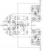
I added the 3.3 pF FB capacitors only to band limit the amp in case of spurious pick-up from the speaker cables. Some FM tuners 10.7MHz can radiate IF and the amp can still operate at that frequency.
Regards
Nico
Hi Nico,
You posted this a while ago - Post #320.
Did you change the C12 & C13 from 12pF to 3.3pF?
You also said that you would implement some of the MiiB's changes, can you please post your latest schematics?
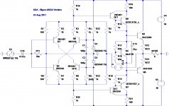
I plan to build the SSA with one pair of L-MOSFET running with 38V DC rails.
I will change AlexMM's layout a bit so that I can use 30mm (10000uF/50V) caps.
Best regards, Stanley
Alex, so this is now schematic from post 217 ?
Alex mm, well done!
By which schematic this was done PCB?
Regards
The upper one, from post #401, that is the SSA from my latest listening test.
")
It is almost the same as from #217, only emitter resistor is added to Vbe multiplier to track tempco more accurately. Otherwise the same sch.
Last edited:
......and now rev 1.5 for BIGBT variant ......
Alex.
Hey what happened to the bigger version ....?
Hey what happened to the bigger version ....?
Be little patient, we have only "The one and only" Alex here.
Member
Joined 2009
Paid Member
I like your approach, Bigun. Very elegant, and the emitter driver output will have low impedance and drive the output stage very well.
Let's see, base to rail resistor for predriver would be 1K, we could run the driver quiescent at around 30mA, and this means, assuming cascode current is 2mA, the predriver emitter to rail resistor would be 47R. With a Zout at each driver emitter of around 1R, you'd have enough drive to propel the USS Nimitz, and of course nice local feedback around the driver circuit. One change, however; I'd put a 1K resistor from emitter to base on each driver to ensure residual current at all times through the predriver.
Cheers,
Hugh
PS I'm not dead sure of the cascode current, but 2mA seems about right to me.
Hugh
Thanks Hugh for that input, it does indeed need these things to flesh out the design and it's good to know that you also have some confidence in this version.
Changes!?
Hi Lazy Cat (Hi Slovenija)!
I have a few questions about this amplifier.
Is it can replace the bias transistor BC550C with BD139 (better is to mount the fridge) or some are needed changes?
For the output transistors can be used ate MJ15003/MJ15004?
In the end, I ask you in a few sentences if you are able to explain how this amplifier?
It will be interesting for electronic amateurs!?
thanks and cheers !
Last edited:
Hey what happened to the bigger version ....?
That's what happens when we have a thread with 100 schematics and neither of them has a clear, distinctive name...
The best we can do now is to refer to them by post number.
Hi Lazy Cat (Hi Slovenija)!
I have a few questions about this amplifier.
Is it can replace the bias transistor BC550C with BD139 or some are needed changes?
For the output transistors can be used ate MJ15003/MJ15004?
In the end, I ask you in a few sentences if you are able to explain how this amplifier?
It will be interesting for electronic amateurs!?
thanks and cheers !
Hi there
I will check both Vbe/temperature curve dependency and if OK, than we could use BD139 because of an easier fixation to the main heatsink.
MJ15003/MJ15004 are "strong" enough, have small hFE + gain bandwidth but it would work, though I have never used them in fast CF amp as SSA is.
That's what happens when we have a thread with 100 schematics and neither of them has a clear, distinctive name...
The best we can do now is to refer to them by post number.
It is basically an educational thread so that's the only way to do it. Maybe you've noticed that when it is the post with schematic published, I put always a different SSA name of the post and the yellow exclamation mark.
Hi there
I will check both Vbe/temperature curve dependency and if OK, than we could use BD139 because of an easier fixation to the main heatsink.
MJ15003/MJ15004 are "strong" enough, have small hFE + gain bandwidth but it would work, though I have never used them in fast CF amp as SSA is.
What you propose transistors in TO-3 casse because i have a large refrigerator for this type transistors!
Regards
I have MJ15024/MJ15025 that are better?MJ15003/MJ15004 TO-3 devices are conditionally acceptable, if you have them, you can give them a try, but I suggest to use more modern semiconductors for SSA design, because of its essence comming from the bandwidth.
thanks
P.S.
I expect an answer and the other my questions?
Last edited:
Member
Joined 2009
Paid Member
Hi All,
I think there are three "tested" schematics here, the L-MOSFET, Michael's (MiiB) BJT version and Andrej's IGBT version.
If I may suggest that Alex would could start a thread where his PCB layout and the associated "tried" schematics are posted for those who want to build and try this superb design for themselves without having to search 400+ posts, but keep that thread totally uncluttered of comments other than PCB layout comments.
Why I am suggesting Alex if he has the time is that he is the only one that has a schematic and BOM that matches up with a PCB on his computer.
Discussions and new ideas remain here on this thread. Any comments on this suggestion?
Regards
Nico
- Status
- This old topic is closed. If you want to reopen this topic, contact a moderator using the "Report Post" button.
- Home
- Amplifiers
- Solid State
- Simple Symetrical Amplifier