LC,
You nailed it expertly..... that's exactly how Roender does his driver, but I think he uses 18R, not 16R - so essentially, your solution is identical.
Hugh
Original was 16R @ 77mA, but 12R, and 100mA as the latest version. I don't want 3 output pairs - only one. With the cfp, I think you need more than the two diodes for biasing/thermal comp..
Sheldon
Member
Joined 2009
Paid Member
I also don't want 3 output pairs, one is enough.
The CFP doesn't add more Vbe's into the mix for thermal comp because the slave device is under the control of the master device before it. Keeping in Class A is important but this seems to require the use of a quadruple output stage - not sure if that's wise ?
The CFP doesn't add more Vbe's into the mix for thermal comp because the slave device is under the control of the master device before it. Keeping in Class A is important but this seems to require the use of a quadruple output stage - not sure if that's wise ?
LC,
You nailed it expertly..... that's exactly how Roender does his driver, but I think he uses 18R, not 16R - so essentially, your solution is identical.
Hugh
Yeah it is simple as that.
")
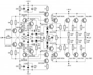
I just combined SSA front-end with Roender's output stage to show how simple is to play within certain topology and it is just a matter of our imagination what the limits are.
I also don't want 3 output pairs, one is enough.
The CFP doesn't add more Vbe's into the mix for thermal comp because the slave device is under the control of the master device before it. Keeping in Class A is important but this seems to require the use of a quadruple output stage - not sure if that's wise ?
Believe me, my understanding of this is very shallow. But connected as LazyCat has shown, requires two pair for the 4 diodes, as there is an extra diode drop over the sc3788/sa1478. However, with the same output buffer, Roender used 5 diodes (4 are under compensated), which means 3 pair of outputs are required. Could use other diodes, but that defeats the purpose of the Thermaltrak.
Is there another way to do this? Otherwise, I'd just go with LazyCat's original thermaltrak version.
Sheldon
Last edited:
Is there another way to do this? Otherwise, I'd just go with LazyCat's original thermaltrak version.
Sheldon
Normally with thermal track BJT's, integrated diodes are used to compensate the thermal drift, how many diodes will be in the bias loop depends on two factors:
- correct DC voltage to set the output stage quiescent current
- thermal drift cancellation
So if Roender used five TT diodes in this output stage than you could do the same. For the DC bias voltage purposes four of them plus 500 ohm trimmer are enough.
If someone would like to use regular BJT's as output devices, than Vbe multiplier should be implemented instead of serial TT diodes. This solution also requires some fine adjustments to cancel thermal drift to minimum.
Last edited:
Has anybody made a PCB for a single pair BJT version?
Not yet.
Until now three PCB's were made:
- post #224 dual mono PCB, Nico's version according to Nico sch, one pair 2SJ162/2SK1058 laterals
- post #227 single mono PCB, Alex's version according to Nico sch, one pair 2SJ162/2SK1058 laterals
- post #301 single mono PCB, Alex's version according to Miib sch, three pairs 2SJ162/2SK1058 laterals
There are quite a lot sch proposals and for an "all BJT's" version we have to make a consensus for the one Alex could possibly design as a thread request.

Please put down your suggestions which sch we should pick to make another PCB. My would be for the last one ...
Last edited:
Can this amp be done with 2SK1530/J201?
Any thought or doubt against why not to use them?
Hi Lazy Cat,
Interested with the one on post#183 PCB because of its simplicity and few parts all BJT, pls let me know also how to adjust to your recommended bias, dmm is the only available instrument. Not so concerned abt the THD figure only the described sound quality is enough for me aside from very few parts n will be easy for me to do.
Thanks alot.
Member
Joined 2009
Paid Member
Not yet.
Until now three PCB's were made:
- post #224 dual mono PCB, Nico's version according to Nico sch, one pair 2SJ162/2SK1058 laterals
- post #227 single mono PCB, Alex's version according to Nico sch, one pair 2SJ162/2SK1058 laterals
- post #301 single mono PCB, Alex's version according to Miib sch, three pairs 2SJ162/2SK1058 laterals
There are quite a lot sch proposals and for an "all BJT's" version we have to make a consensus for the one Alex could possibly design as a thread request.
Please put down your suggestions which sch we should pick to make another PCB. My would be for the last one ...
I think you have my vote already - CFP driver stage for BJT outputs. I grant that it's more complex but it gives the flexibility for higher power and for use with lower impedance loads.
I think the simpler all-BJT design is also an attractive option, perhaps more popular than what I'm seeking. And a noble goal is to encourage people to build, which the simpler version might be better at doing.
Of course, one solution would be to have both

Normally with thermal track BJT's, integrated diodes are used to compensate the thermal drift, how many diodes will be in the bias loop depends on two factors:
- correct DC voltage to set the output stage quiescent current
- thermal drift cancellation
So if Roender used five TT diodes in this output stage than you could do the same. For the DC bias voltage purposes four of them plus 500 ohm trimmer are enough.
As I understand it, if the diodes had the same characteristics as the transistor junctions, then one diode per transistor diode drop, plus a small amount of series resistance, should be enough to bias the outputs and also compensate for thermal drift. But it appears that the tt diodes are not an exact match for the transistors. Or perhaps the mismatch is with the cfp junction. Hence, five diodes instead of four for Roender's output buffer.
Perhaps your schematic with a single output pair would be adequately compensated.
Sheldon
I think you have my vote already - CFP driver stage for BJT outputs. I grant that it's more complex but it gives the flexibility for higher power and for use with lower impedance loads.
I think the simpler all-BJT design is also an attractive option, perhaps more popular than what I'm seeking. And a noble goal is to encourage people to build, which the simpler version might be better at doing.
Of course, one solution would be to have both
Maybe both on the same board? Just populate for which one is preferred. Same would apply for multiple outputs. Don't have to populate them.
Sheldon
Hi all,
Thanks for the interesting work.
I have a set of the world's most demanding speakers (Apogee Sinctilla). Impedance drops to 0.4 ohms on the mid range ribbon.
Would it be possible to use this amp with several paralleled output devices to drive such a difficult speaker?
What about using ut to drive 50ohm headphones?
Apologizing for a late answer, but only now with the last schematic present, we have a solution to address your issue. SSA in the last incarnation can drive low impedance loads without a struggle and for such special cases like yours, it is even possible to double the number of output devices to handle below 1 ohm speakers. Also because of the SSA's special current feedback loop, phase, time and frequency accuracy are there to fulfill your demand for a sound details capability. We only need to wait that "someone" will win the battle with PCB design for the rest of us.
Last edited:
As I understand it, if the diodes had the same characteristics as the transistor junctions, then one diode per transistor diode drop, plus a small amount of series resistance, should be enough to bias the outputs and also compensate for thermal drift. But it appears that the tt diodes are not an exact match for the transistors. Or perhaps the mismatch is with the cfp junction. Hence, five diodes instead of four for Roender's output buffer.
Perhaps your schematic with a single output pair would be adequately compensated.
Sheldon
For six TT outputs like in present topology all six diodes would overcompensate thermal drift, four serial TT diodes would fulfill voltage criteria, but five are according to Roender's experiences just right. This is the least critical part of the design and can be made as selectable on PCB.
Last edited:
The Roender style output stage had a variable temp co.
He chose the diode current to fine tune the temp co. to what the triple required.
If you go for a 2pair output stage then only 4diodes are available.
I think you will find that the temp co. @ Roenders diode current will be under-compensated. However, I seem to recall that increasing the diode current (more VAS current) brings the temp co. back up again.
The Roender style output stage had a variable temp co.
He chose the diode current to fine tune the temp co. to what the triple required.
If you go for a 2pair output stage then only 4diodes are available.
I think you will find that the temp co. @ Roenders diode current will be under-compensated. However, I seem to recall that increasing the diode current (more VAS current) brings the temp co. back up again.
Actually, I want a single output pair. With LazyCat's single pair version, it may be slightly undercompensated. I guess that one could experiment with an additional diode of various types to dial it in. If the diode is mounted to one of the outputs, it might be good enough.
My experience with Roender's amp, is that the compensation is fine. Little drift during warm up. The VAS current (2mA) was not changed from the original schematic (he did give an option for higher driver current).* In fact, the added series resistance, when adjusted for about 18mV at the emitter, is only about 50R. I built two amps. The tt diodes do show some variation. In one channel, I had to bypass a particular diode out of the six to be able to set the bias.
*In LazyCat's single pair version, the current through the diode string is significantly higher, so perhaps two diodes may be adequate there. And for the same reason, maybe 4 diodes for the cfp version would be fine.
Sheldon
Last edited:
Has someone checked the output offset stability in respect
of temperature variation ?..
So far, the sims say that the shift is about 100mV/25° , that is 4mV/°C.
A servo can be necessary.
At this case simm is wrong.
I extensively push hard the temp of the whole amp stages and there is none offset temperature dependency. I measured max deviation of +/-10mV DC at output pin, also explained this in some previous post already, so no DC servo required.
Last edited:
- Status
- This old topic is closed. If you want to reopen this topic, contact a moderator using the "Report Post" button.
- Home
- Amplifiers
- Solid State
- Simple Symetrical Amplifier