Some other research papers show that 180 mA for 2SK1058 and 2SJ162 as output devices indicates least distortion.
For the last requirement would of course require Vbe multiplier, in the current circuit it is not necessary. I have designed with MOSFET driving BJT but thermally it has never been stable without it. What are your suggestions.
For the last requirement would of course require Vbe multiplier, in the current circuit it is not necessary. I have designed with MOSFET driving BJT but thermally it has never been stable without it. What are your suggestions.
I know, look to my pic of my test bench, and there it is, Vbe multiplier sitting on the top of BIGBT. I know it is one more transistor in sch, but it works perfectly. As I metioned before, the BIGBT temperature went well over 60°C, because of the signal present on 6 ohm load at the output (no thermal runaway) without any heatsink, and bias current was still perfectly stable.
Maybe we should first simulate:
- BJT driver/mosfet output
- mosfet driver/BJT output
to see which combination sounds the best and than we can surely decide about the need of Vbe multiplier.")
Maybe we should first simulate:
- BJT driver/mosfet output
- mosfet driver/BJT output
to see which combination sounds the best and than we can surely decide about the need of Vbe multiplier.
With BJT following MOSFET distortion seems significantly worse. Maybe you have some clues.
I see an even harmonics much more present in distortion distribution than odd ones, maybe this is the reason why the amp sounded very pleasant. The average level can be lowered significantly by proper biasing of both stages.
Thanks Hugh, it is purely my idea.
It`s a Hawksford LFD preamp concept, but nice circuit anyway.
http://www.essex.ac.uk/csee/researc...bdocs/G11 Sound the charge HFN LFD preamp.pdf
Lazy Cat, it would certainly help if you could also post the biasing circuit and the full schematic of the BIGBT version. Building, comparing notes and observations, both actual listening and simulation would become easier and practical. Thanks.
Nico, great work as always.
Nico, great work as always.
It`s a Hawksford LFD preamp concept, but nice circuit anyway.
http://www.essex.ac.uk/csee/researc...bdocs/G11 Sound the charge HFN LFD preamp.pdf
I see
Thanks for the link, I see it for the first time, but who would believe me.
Lazy Cat, it would certainly help if you could also post the biasing circuit and the full schematic of the BIGBT version. Building, comparing notes and observations, both actual listening and simulation would become easier and practical. Thanks.
Nico, great work as always.
Yes I know it would help, but all circuit is so simple that by reading this thread, you can find all the parts posted and like LEGO you can easily connect them to mine version.
Will do that when come back to the cockpit from the vacations. Enough hand drawing for now.
More about BIGBT's in this thread:
http://www.diyaudio.com/forums/solid-state/134789-balanced-igbt-amplifier-output-17.html
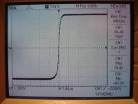
On the pic you can also see what is possible to get at the output of my simple symmetrical amp with BIGBT's incorporated.
Attachments
Lazy Cat, it may be placebo effect, but I think that the Lateral MOSFET with transistor driver sound better subjectively, it is slightly better balance overall than your half IGBJT but hard to tell for sure, I have issues whith getting the bias quite right on the IGBJT,
My last test that shows a definitive difference by making a synchronized recording of both topologies on either channel of the storage scope and perform X - Y, Although they sounds in many ways, the difference on the scope jumps out at you as being radically different.
On my version all the harmonics are present but in much lower amplitude and causes a very smooth transition between notes. In your latest suggestion you have predominant but much higher even order products and sound warmer.
My humble conclusion is:
1st Circuit a little harsh, clean and highly defined.
2nd version with BJT driving Mosfet is totally neutral sounding a little laid back and relaxed
3rd version with MOSFET driving BJT sounded very warm and even too relaxed drum boom but not thud as with the previous two. Although sounding great, it is difficult to split a big bass drum from a low electric bass, on the other two this definition is more easily detected.
Make of my findings what you like, it is subjective. Same set-up, same music piece, slightly different experience,
The fire-walk will be is to set-up and blind test the three topologies and try to establish which has the broadest i9mpact on the listener. Because we are from different cultures our experience will differ thus may I suggest we do these tests on each side of our world and compare the outcome - subjectively of course when we reach a conclusion. We stick with the version that indicates to be most acceptable and offer this as the BETTER THAN GOLDMUND, I think that one of these three topologies will topple that throne.
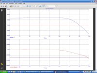
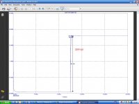
Yes it is. Here is BJT driving MOSFETThis graph Nico got from sim is somehow related tu upper plot or am I wrong.
Attachments
Excellent job Nico, hats off. 
I agree completely, cause it is much simpler to say: OK we have the best version, let's do it, bang boom PCB that's it.
But no, we will certainly perform listening test, like you said in different cultural environments and pick the winner. I like the idea very much Nico.
By reading your post one idea fallen on the top of my head, what if BJT+BJT would also be the one to include it in the test and rule out the first one which incorporates only mosfet (1st Circuit a little harsh, clean and highly defined). So the 1st is now BJT driving BJT, this one could have all the goodies from the 2nd 3rd. Agree?
All in all the basic circuit inside current feedback loop proven to be stable in all three versions and can be easily adopted as universal to many more complex circuitry including current sources/mirrors et cetera.
And finally, yes BETTER THAN GOLDMUND is going to be.
This graph Nico got from sim is somehow related tu upper plot or am I wrong.
Yes it is. Here is BJT driving MOSFET
OMG speed and stability, that's the way we like it.

So quite obviously for now BJT driving mosfet is in the lead, considering listening tests and sim performance.
Attachments
Last edited:
- Status
- This old topic is closed. If you want to reopen this topic, contact a moderator using the "Report Post" button.
- Home
- Amplifiers
- Solid State
- Simple Symetrical Amplifier