Input layout should be taken with care on All wideband amps.
If such a 10Mhz signal is to large you Will end up destroying the output devices. Parasitic caps (even af few nf) Will pull a lot of current and destroying the silicon.
In my amps i Pick up the rf from the oki/metcal solderiron.
Just be carefull.. Nice to hear it works well for you.
I have criticism your layout but it looks good when build.i just hope you dont need to repair it!!
So far it works perfectly and that's only basics here, the most important is its "sound"

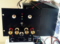
For RF's suppression sake I put 100 ohm/100 pF low pass filter at the input.
For me the improvement in subjective sound quality is very clear with stronger bias.
It's logical also. First few watts pure class A, no switching. When o/p devices finally switch the switching noise is masked out by the the sheer volume of music.
2nd HD might rise a little but higher harmonics / noise should reduce.
Result is more musical.
500mA is my minimum.
It's logical also. First few watts pure class A, no switching. When o/p devices finally switch the switching noise is masked out by the the sheer volume of music.
2nd HD might rise a little but higher harmonics / noise should reduce.
Result is more musical.
500mA is my minimum.
2nd HD might rise a little but higher harmonics / noise should reduce.
Result is more musical.
500mA is my minimum.
OK I will start with 500 mA per device (1A current x 120 V supply voltage is 120 W quiescent power dissipation) and than will lower a little (to 100 W) if the heatsink temp will be over 55°C.

More musical you say, mmmm nice.
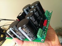
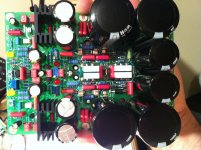
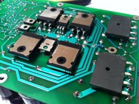
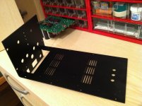
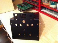
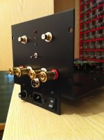
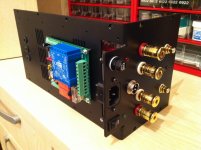
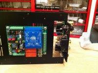
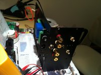
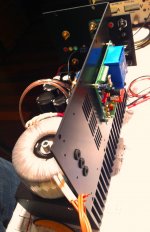
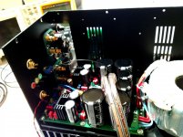
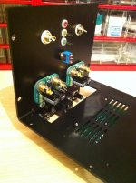
Few more pics from today's assembly.
Attachments
Last edited:
Member
Joined 2009
Paid Member
Looks very nice - the cat is not so lazy eh ?
Thanks Gareth
Well I could do more but still there's job plus family etc. Still have to get bottom plate with standing pads, front plate, plus top cover. At the end it won't be a very big case, you'll see, some 30 x 30 x 13 cm only but the weight will be more than 20 kg.
I need well built serious power amplifier for my Avantgarde Trio speakers. It has to be fast, perfectly silent, 20 W/20 ohm A-class amplifier, since speakers have 109 dB/1 W /1 m efficiency.
Last edited:
Very organized assembly. The evolution from SSA to CSA=Complex Symmetrical Amplifier?
The evolution from SSA to CSA=Compact Symmetrical Amplifier
Maybe less but certainly more than 100 dB/1 W/1 m. Trio alone, but still two more horns in the room to feed ...
Stereo SSA will have 5 PCB-s:
- two SSA Channel PCB
- two SSA DC Sense PCB (at output terminals)
- one SSA Soft Start utility PCB
I'll do complete parts count plus costs summarization when listening the amp in my system, at that point will be my pleasure to do something more for DIY-ers potentially interested to build something like this.
Listening carefully, it is not so obvious. Increasing output bias, there is a point after witch i cannot notice any real improvement. And may-be after this point, a slight degradation in dynamic feelings. Some audiophile believes that A class is the Graal. On my side -it is a personal point of view- i consider-it as a waste of money and electric energy.For me the improvement in subjective sound quality is very clear with stronger bias.
Also, it seems to me that this ideal bias current depends more on the power device technology (Bipolar or FET) than on the schematic of the amp.
Yes type of used output devices demands its own approach, best practically tested as you and many did, agree. Looking from mine point of view now having this very efficient heatsink 150 mA of bias would lead outputs to be slightly warmer than ambient and that's not really good as I experienced that BJT outputs best operate around 45-50°C. Also hFE is a little bit higher at this temp. So to my opinion we should follow two conditions, bias current to be higher than 150 mA/device plus operating temperature around 45-50°C and both are inevitable dependable to heatsink dissipation characteristic. I will experiment to get optimal operating conditions, make sound checks and than report.
Listening carefully, it is not so obvious. Increasing output bias, there is a point after witch i cannot notice any real improvement.
Could you tell us what the current is above which you cannot notice improvement - thx
LC, there are some stability problem regards thermal with my amplifier after using 2SA1707/2SC4487. The VAS bias varies more (could say fluctuate) than the previous MJE.
Without using heatsink, the thermal condition of both VAS are different. (because no thermal coupled) Is this possible source of degradation I head ?
At the same time, the VAS bias varies alot when I changed into other speakers, from 2mA to 10mA and continue to increase due to temperature. (dunno what is causing this)
Is there any other technique for VAS thermal stability ?
Guitar obviously we cannot pass VAS transistors at all. I think it will be our conversation topic forever ... 
Look I will tell this again: please use TO-126 case transistor for VAS or VAS cascode and use heatsink which will dissipate 1W of power at max 45°C (22°C ambient + 23°C extra temp regarding power dissipation). Than and only than you will get stable VAS conditions.
2SA1707/2SC4487 are not proper choice since their case is not suitable for normal heatsink.
And again I will tell you, please get 2SA1209/2SC2911 for good VAS response.
Could you tell us what the current is above which you cannot notice improvement - thx
It is not quiescent current what is important in case of BJT OPS but the voltage between emitter resistors. Look in Audio Power Amplifier Design Hanbook by D. Self.
- Status
- This old topic is closed. If you want to reopen this topic, contact a moderator using the "Report Post" button.
- Home
- Amplifiers
- Solid State
- Simple Symetrical Amplifier