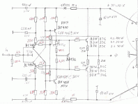
hm.... i'm thinking is there any other replacement for them at the input ? I personally favor 'On Semiconductor' 's transistor, good if any recommendation ?You can replace the front end transistors with BC550,560, with no changes to the front end components. BD139/140 can replace the 2SA1478/2SC3788, with no change. The larger part is used because they can dissipate more heat than the front end TO99 parts, and you can run more current through them to drive the outputs.
Sheldon
I was thinking, if I were to put other transistor same as output transistor, is there any disadvantage (other than money aspect) and what is the advantage ?
Example : all transistor using NJL3281/1302 pair where NPN & PNP are correct position
Last edited:
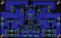
Marc very good PCB you've made here. 
If you didn't order them yet I suggest you to take NJL4281-NJL4302 because of their higher current gain (hFE) noted in datasheet.
In a real case of a 5A output (speaker) current VAS transistors (T1, T2) would have to provide 20mA signal current to the bases of the output transistors (at hFE=250). So for an amplifier design simple as this all transistors have to be at their best performance level (max hFE) to get lowest distortions possible.
I hope you will use this amp to drive speakers with impedance curve of more than 4 ohm.")
P.S. VR2 should be 100 ohm trimmer. It will be set to 8,8 ohm at Iq(VAS)=5mA and Iq(OUT)=100mA (hFE=250).
What about choice between NJL3281/1302 and NJL4281/4302?
If you didn't order them yet I suggest you to take NJL4281-NJL4302 because of their higher current gain (hFE) noted in datasheet.
In a real case of a 5A output (speaker) current VAS transistors (T1, T2) would have to provide 20mA signal current to the bases of the output transistors (at hFE=250). So for an amplifier design simple as this all transistors have to be at their best performance level (max hFE) to get lowest distortions possible.
I hope you will use this amp to drive speakers with impedance curve of more than 4 ohm.
P.S. VR2 should be 100 ohm trimmer. It will be set to 8,8 ohm at Iq(VAS)=5mA and Iq(OUT)=100mA (hFE=250).
Last edited:
Marc very good PCB you've made here.
If you didn't order them yet I suggest you to take NJL4281-NJL4302 because of their higher current gain (hFE) noted in datasheet.
In a real case of a 5A output (speaker) current VAS transistors (T1, T2) would have to provide 20mA signal current to the bases of the output transistors (at hFE=250). So for an amplifier design simple as this all transistors have to be at their best performance level (max hFE) to get lowest distortions possible.
I hope you will use this amp to drive speakers with impedance curve of more than 4 ohm.
P.S. VR2 should be 100 ohm trimmer. It will be set to 8,8 ohm at Iq(VAS)=5mA and Iq(OUT)=100mA (hFE=250).
Ok thanks Lasy Cat. I will have 5 couple of each. It will be eventually for Home theater 5Ch in small room (15m²). These bord will make a compact size 5ch amp. The speakers doesn't normally goes under 5Ohms. Thanks for value advices. 5k on biasing pot is a device copy mistake.
Marc
Last edited:
there is no way the ONsemi nor any other BJT can maintain 250hFE @5A of Ic.
Look at the typical graphs that ONsemi show in the datasheet. Then allow for the variation of hFE that is quoted in the table as min, typ, max.
Expect a range of hFE @ 5A Ic of about 80 to 120 resulting in a base current of 42mA to 62mA.
Now add on the driver's emitter resistor current.
That is what the driver must supply just to feed a resistive load with 5Apk output current.
AndrewT thanks for your calculations and support. Of course an output transistor with hFE=250 is hard or even impossible to find, but my calculations at given data were correct completely. I intentionally presented top level results to show what conditions we are coping in ideal case, as a top reference of what is possible to achieve. Some would also use outputs with hFE=40 but as I already stated, that is not recommended in this simple design.
hm.... i'm thinking is there any other replacement for them at the input ? I personally favor 'On Semiconductor' 's transistor, good if any recommendation ?
I was thinking, if I were to put other transistor same as output transistor, is there any disadvantage (other than money aspect) and what is the advantage ?
Example : all transistor using NJL3281/1302 pair where NPN & PNP are correct position
One suggestion for you guitar89, try to built one of the simple SSA amp design and than play with different types of BJT's to get the performance you like. In general it is very important to chose BJT's with high current gain (hFE) value and you will be rewarded with great SSA sound.
AndrewT thanks for your calculations and support. Of course an output transistor with hFE=250 is hard or even impossible to find, but my calculations at given data were correct completely. I intentionally presented top level results to show what conditions we are coping in ideal case, as a top reference of what is possible to achieve. Some would also use outputs with hFE=40 but as I already stated, that is not recommended in this simple design.
I am looking forward to your future work on even simpler front end such as attached. My darlington transistors have hFE 15K-30K, fT 60MH, Co 55pF. But why would this topology not suitable for ordinary output transistor?
Attachments
hFE at what current?darlington transistors have hFE 15K-30K,
How does the effective hFE vary with current?
Integrated Darlingtons in my little experience do not behave as linearly as discrete, driver & output pair when well designed. You must not omit the driver emitter resistor and preferably the driver current must be decades higher than in an integrated Darlington.
hFE at what current?
How does the effective hFE vary with current?
Integrated Darlingtons in my little experience do not behave as linearly as discrete, driver & output pair when well designed. You must not omit the driver emitter resistor and preferably the driver current must be decades higher than in an integrated Darlington.
hFE @ Ic=5A, Vce=4V, that's what the spec says. Of course, it is just for rough relative comparison with other darlingtons, not with ordinary BJT.
I think all darlingtons have driver emitter resistor (in this case 70 Ohm). It is the driver's base-to-emitor resistor that sometimes omitted. What is the benefit of this Rbe?
I'm finding some excellent input transistor, so please help me see if it is compatible ?
http://www.datasheetcatalog.org/datasheet/fairchild/BC547.pdf
I guess using BD139/140 pair is good enough for VAS driver ?
I will also use BC550/560 pair, should I get BC550A/B/C (gain different).http://www.onsemi.com/pub_link/Collateral/2N5087-D.PDF (good noise figure)
http://www.onsemi.com/pub_link/Collateral/2N4403-D.PDFQuoted from other site: The compound pairs of 2N4403 and BC549s are far more linear than any single transistor.
http://www.datasheetcatalog.org/datasheet/fairchild/BC547.pdf
I guess using BD139/140 pair is good enough for VAS driver ?
Any thoughts on using 2SJ201 & 2SK1530 output MOSFETS with a +/- 45 rail? Thats my option of parts readily available. Also either MJE 340/50 or BD 139/40 as drivers? The basic design has a simplicity that really captured my attention! Thinking about using it as a monitor amp for my home studio.
I have another 'candidate' for VAS driver, to replace 2SC3788/1478 pair.
NJL0302/0281
NJL1302/3281
NJL4302/4281
Hope my ear is good enough to listen the difference. Any advise on those transistor replacement ?
About Output transistor, I'm going to try all NJL thermal track series I know, such asBD787/788 pair :
https://www.onsemi.com/pub/Collateral/BD787-D.PDF
MJE15030/15031 pair :
https://www.onsemi.com/pub/Collateral/MJE15028-D.PDF
NJL0302/0281
NJL1302/3281
NJL4302/4281
Hope my ear is good enough to listen the difference. Any advise on those transistor replacement ?
I had a looked into datasheet of BC550C/560C, but they have some different (other than polarity) parameter, such as gain, voltage, noise figure. Is it abnormal ?
Noise figure : 0.6 (while another is 0.5)I can see a misprint in the units of small signal gain.
I think the 380 is also a misprint for the min DC gain.
Which parameters are you saying are different.
Andrew,
what would you recommend from the below transistor to be used ?
I personally felt putting BC550 pair as input (low noise !)
then BD139/140 or MJE15034 pair as VAS driver.
Finally NJL4281/4302 or NJL0281/0302 or MJL21193/21194 as OUTPUT transistor.
I should say that is the combination i'm going to try out. Any advice would be welcome ^^
what would you recommend from the below transistor to be used ?
Any other better recommendation to replace them ? (n place of input, driver & output)BD139/140 : www.fairchildsemi.com/ds/BD/BD135.pdf
BC550/560 : http://docs-asia.electrocomponents.com/webdocs/078e/0900766b8078ea68.pdf
MJE15034/15035 : http://www.onsemi.com/pub/Collateral/MJE15034-D.PDF
MJL21193/21194 : http://www.onsemi.com/pub/Collateral/MJL21193-D.PDF
NJL4281/4302, NJL0281/0302 : Someone claim NJL0281 pair sounds better than NJL3281 (although technically inferior in power), then what about NJL4281 pair ?
I personally felt putting BC550 pair as input (low noise !)
then BD139/140 or MJE15034 pair as VAS driver.
Finally NJL4281/4302 or NJL0281/0302 or MJL21193/21194 as OUTPUT transistor.
I should say that is the combination i'm going to try out. Any advice would be welcome ^^
- Status
- This old topic is closed. If you want to reopen this topic, contact a moderator using the "Report Post" button.
- Home
- Amplifiers
- Solid State
- Simple Symetrical Amplifier