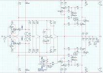
the OUT location is wrong. You show it from the top end of L1.
It should be OUT at the top of R27/bottom of L1
O.k. thanks, I'l change that, any more fixes or improvements?
My http://www.diyaudio.com/forums/solid-state/193923-simple-symetrical-amplifier-106.html#post2735781 can be found here.
O.k. thanks, I'l change that, any more fixes or improvements?
A few small corrections have been made, but the (my) main question is still open: Why is the DC-servo not doing its work? Why does offset change (a lot) with load impedance? Anyone... and how to correct it?
Update: Woops, the drawing has one error, v15n(out) has been connected to ground and should be connected to -15V. (Offset problem unchanged
 )
)Attachments
Last edited:
Member
Joined 2009
Paid Member
My guess: You have the dc servo in parallel with a dc global negative feedback loop - they will fight to control the dc offset. And the dc servo will lose because it's fed via 22k resistors - a higher impedance than the global feedback loop. Most likely you have to choose which one will be boss - and if you want the servo then the global feedback must be broken with a capacitor somewhere.
My guess: You have the dc servo in parallel with a dc global negative feedback loop - they will fight to control the dc offset. And the dc servo will lose because it's fed via 22k resistors - a higher impedance than the global feedback loop. Most likely you have to choose which one will be boss - and if you want the servo then the global feedback must be broken with a capacitor somewhere.
Thanks Bigun.
But it works (partly), for a 4ohm load the offset goes to zero, for the other loads the offset is way lower that without the DC-servo. Essentially the DC voltage at the measuring point is zero (for all loads) and the servo is doing some work, I cannot see that this is the full answer (but it could). If the servo can not be hooked up to this point, where then?
Additionally; changing the 22K’s to 5K’s has no effect on the offset values. Only the amount of ‘Servo authority’ as DSelf calls it.
Member
Joined 2009
Paid Member
If I understand correctly (?)...To affect the dc offset you need to change the potentials at the emitters of Q1 and Q4. In your design there are 3 things controlling this potential. 1) the global feedback, which via R17 has an impedance of 1k. 2) the 'current source' formed by R2, also 1k impedance, 3) the dc servo, at best 5k impedance in your latest simulation.
For the dc servo to have control here I'd suggest it needs to have a lower impedance. The opamp should be able to drive it.
An alternative is to implement the dc servo differently. Instead of feeding the output of the servo directly into the feedback loop, you could replace R2 by an active current source and use the dc servo to drive that current source. I remember Hugh Dean has used this technique from a picture he posted somewhere on this forum (I can't remember where - it was in a thread by OStripper I think).
p.s. a low impedance op-amp driving into the feedback node will affect gain, it will reduce the -ve fdback factor, it maybe a case of 'you can't get there from here'
Last edited:
If I understand correctly (?)...To affect the dc offset you need to change the potentials at the emitters of Q1 and Q4. In your design there are 3 things controlling this potential. 1) the global feedback, which via R17 has an impedance of 1k. 2) the 'current source' formed by R2, also 1k impedance, 3) the dc servo, at best 5k impedance in your latest simulation.
Bigun thanks again, I tested this, not by changing the DC-servo or it’s hook up, but by taking away the competition. Adding 100uF capacitors in series with R17 and R18 removes DC control from the ‘normal’ feedback loop and gives total control to the DC servo, again nothing changed.
LazyCat, thanks for the Low Z amp! Do you think it will be stable into 0.5R loads? Any empirical evidence?
You may have to double the output stage to do so or add an .5 ohm wire wound resistor block in series.
Just saying ....
Bigun thanks again, I tested this, not by changing the DC-servo or it’s hook up, but by taking away the competition. Adding 100uF capacitors in series with R17 and R18 removes DC control from the ‘normal’ feedback loop and gives total control to the DC servo, again nothing changed.
But then again, I may be a idiot
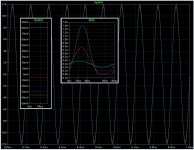
. I checked the DC operating points for all load values that I was testing (16, 8, 4 and 2Ohm) and found that the DC offset was near 600uV, and that is fine. The offsets that where worrying me where in the output signal (see attached picture) it shows different ‘zero crossing offsets’ at V(n007) for each load, -35mV for 16Ohm, -30mV for 8Ohm, +5mV for 4Ohm and +80mV for 2Ohm. And also large variations in ‘zero crossing offset’-currents at I(R9), one of the power transistor emitters (the bias measurement point).Why would that be?
Attachments
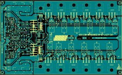
.....thanks ,I hope this time it's better layout
Alex.
Great looking SSA amp module, congratulations Alex.

This is really unexpected gift to the DIY community and it will serve the job with all demanding speakers as intended. Please give me some time to check the layout & connections and then give the error list to you. I'll do it on Friday morning.

You are an artist !.....thanks ,I hope this time it's better layout
Alex.
I had finished my soft start, remote power on, delayed speaker on, differential protection circuit schematic. Improved.
State of the art instant protection for the state of the art SSAs ?
http://www.diyaudio.com/forums/digi...sures-class-d-system-project.html#post2737393
Fully simulated.
Use only 1 Quad Op amp, a dual comparator, a transistor, two static relays and one or two mechanical (or static) ones for the speakers.
Similar design has proven in my own amp to protect in ms against short circuits, HF, DC (down to 300mv) and all kind of failure and parasitics. With no impact on the sonic quality.
Down to 600mv DC in the output can fire the protection in 1 µs.
Schematic is explained in my poor English, apologize.
Attachments
LAZY CAT, ALEX MM, ESPEARADO and ALL CONTRIBUTORS
 A really big thank to You Mr.
  Andrej and to all constructive contributors to this the most elegant SSA Power Amplifier design by Lazy Cat who generously and unselfishly share it here with top of SSAs Amps, a balanced version, this also applies to Mr. Alex MM, who the same as LC unselfishly contribute to a beautiful PCB artistic Art, the same goes to all others of a good will who share theirs experiences and knowledge here for a better enjoyment in music experience of all audio enthusiasts.
Andreas
Great looking SSA amp module, congratulations Alex.
This is really unexpected gift to the DIY community and it will serve the job with all demanding speakers as intended. Please give me some time to check the layout & connections and then give the error list to you. I'll do it on Friday morning.
A really big thank to You Mr. Andrej and to all constructive contributors to this the most elegant SSA Power Amplifier design by Lazy Cat who generously and unselfishly share it here with top of SSAs Amps, a balanced version, this also applies to Mr. Alex MM, who the same as LC unselfishly contribute to a beautiful PCB artistic Art, the same goes to all others of a good will who share theirs experiences and knowledge here for a better enjoyment in music experience of all audio enthusiasts. Andreas
Last edited:
Is it possible to use some substitute BJT onto the simple version ? (I saw mosfet at first page ?)
I have some spare MJL3281 and 1302 pairs, what other component should i change with the change of BJT ? (It would be good if you could provide diagram/link, even better if had simple specification like load available & maximum wattage)
And what is the difference in the ADVANCED(more complicated though) improved SSA, compare to its simple version ? (i only know its power output is more ?)
Last edited:
An amplifier output is determined by the supply voltage and the component capabilities. Even with the simplified lateral MOSFET design you can obtain 300 watt provided you choose capable transistors transistors and you do not exceed 70 - 80V with using the 2SK1058/2SJ162 as well as increase the number of output devices to say six pairs.
I built mine to be 40 watt because it was stuff I had, if you want to purpose build it in a high power version nothing stops you, it is an amazingly musical amp. It may not boast impressive specification but it sounds impecable and this objective was achieved.
I built mine to be 40 watt because it was stuff I had, if you want to purpose build it in a high power version nothing stops you, it is an amazingly musical amp. It may not boast impressive specification but it sounds impecable and this objective was achieved.
Member
Joined 2009
Paid Member
Is it possible to use some substitute BJT onto the simple version ?
this isn't exactly a direct substitution of BJT for FET but maybe an option for you ... it is based on the SSA of this thread by Lazycat
http://www.diyaudio.com/forums/solid-state/196973-tgm5-all-bjt-simple-symmetric-amplifier.html
- Status
- This old topic is closed. If you want to reopen this topic, contact a moderator using the "Report Post" button.
- Home
- Amplifiers
- Solid State
- Simple Symetrical Amplifier