May-be you can add a 4700µF electrolic cap between feedback resistances R17, R28 and ground to increase DC feedback ? (joke)Offset +-5mV(varies all the time).
5mv is a real nothing....
Last edited:
May-be you can add a 4700µF electrolic cap between feedback resistances R17, R28 and ground to increase DC feedback ? (joke)
5mv is a real nothing....
I know esperado. But that is not really the problem, the offset is too much sensitive to slider movement, still.
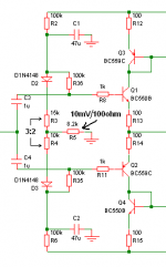
However, I have reached a solution to this problem while using only one pot for offset, still at the input, decreasing slider sensitivity, decreasing parts count and increasing input impedance and power bandwidth. Current through the input BJTs are 5.5mA and 5.8mA. I am attaching the input stage. Please comment.
What I found is that the offset is best controlled at a specific ratio of the resistors R3 and R4. For my instance it is 3:2 and I'm going to test it right away with a 10K pot in place of R5.
Attachments
Last edited:
Then R3= R4=10k and between us a 4.7k pot with the cursor at ground ? It will go for an other pair or an other amp ?
And why to keep D2 and D3 ? If you want to keep them to filter, they would be better between R2 and C1 & R5, C2
Last edited:
Finally, got what I needed! Fine tuning of the offset.
The idea was really simple, I wonder why I didn't think of it first!
VR1 and VR2 is both 10K.
VR2 has about +-500mV offset control over its 10K range, i.e. 1Volt.
Started with both pots at 50%, set VR1 first to about 1volt, then VR2.
That's all and it worked!
However, offset is still dancing between +-5mV.
Simulating SSA now.
Attachments
C5 would be better in the bases of Q1 & Q2. You can make a nice lowpass at 100kz, and it will filter RFI from power supply in the same time (you can use SMPS)
If you are bored by this offset problem, you can, with a simple OP amp, build a DC servo, and get rid of offset as well as tuning-it. I like very much this feature, specialy when your design allow no cap in the input.
Last edited:
Yes I have already played a lot with servos. They are touchstones capable of making any naughty amp behave. I use them in my DoZ amp which are direct coupled and fed from dual supply and are assymetric, so servos were essential.
I am not bored! Come on, did I ever look so? After this much of mess? Don't worry.
I am not bored! Come on, did I ever look so? After this much of mess? Don't worry.
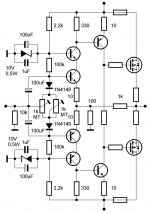
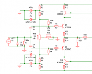
Lazy cat, one idea (sorry, not so easy to read ).
Your input architechture + error correction power stage from Bob Cordell.
i'm sure it would done something very special fast as light and smooth sounding with very low distortion and huge damping with less global feedback.
The best of the two best sounding world ?
Your input architechture + error correction power stage from Bob Cordell.
i'm sure it would done something very special fast as light and smooth sounding with very low distortion and huge damping with less global feedback.
The best of the two best sounding world ?
Attachments
However, offset is still dancing between +-5mV.
Simulating SSA now.
+/-5mV is really nothing, what matters is to look at this in freq domain. Look what I posted to you a while ago:
So for the begining I suggest you to place 15V zeners in parallel to C1, C2, replace VR1 with two 1N4148 + trimmer in series and certainly "must" is thermall coupled input NPN/PNP pair. That would help DC bias conditions to be much more stable.
For a sensitive/high impedance input DC bias control arrangement you need a very stable DC supply rails, so two 10-15V zeners are essential.
DC servo, forget about it.
However, I have reached a solution to this problem while using only one pot for offset, still at the input, decreasing slider sensitivity, decreasing parts count and increasing input impedance and power bandwidth. Current through the input BJTs are 5.5mA and 5.8mA. I am attaching the input stage. Please comment.
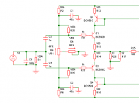
Please try something like this for the input arrangement.
Attachments
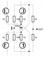
SSA Full Balanced Input
Schematic will explain everything.
What we got here is full balanced input with symmetrical input impedances for positive and negative input and at top of it in current feedback loop arrangement, with minimal parts count.
See attachment, that's what you means ? I just wonder why you want me to change the emitter values from 150 ohms to 10, it increase current and open loop gain, right ? it need 4watts for the 330 ohms then, and, if i'm correct, the gain will be 33 if 330ohms are set to 660 now ?.
Where did you see this 100µF, where i have put the 1000µ ?
Schematic will explain everything.
What we got here is full balanced input with symmetrical input impedances for positive and negative input and at top of it in current feedback loop arrangement, with minimal parts count.
Attachments
Lazy cat, one idea (sorry, not so easy to read ).
Your input architechture + error correction power stage from Bob Cordell.
i'm sure it would done something very special fast as light and smooth sounding with very low distortion and huge damping with less global feedback.
The best of the two best sounding world ?
I see no problem in combining these two together since they operate in logical order. With proper parts calculation such amp would work without any problem.
Please try something like this for the input arrangement.
Will do. ASAP. Looks VERY interesting.
For a sensitive/high impedance input DC bias control arrangement you need a very stable DC supply rails, so two 10-15V zeners are essential.
DC servo, forget about it.
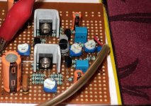
This really works! Although I am not using diodes at pots because of high dissipation in input pair, adding zeners tamed the offset even more!!!
Attachments
I know i am annoying but I am nearly finished with this amp, so the last and important question 1K trimmer is for bias wright?
2K trimmer is for DC-offset at powering on 2K in the middle position?
1K full counter clockwise for minimum bias is that OK I don't wont to mess up at firing on for first time
2K trimmer is for DC-offset at powering on 2K in the middle position?
1K full counter clockwise for minimum bias is that OK I don't wont to mess up at firing on for first time
2K trimmer is for DC-offset at powering on 2K in the middle position?
2k trimmer starting position is at 1k value ie. middle position. I recommend multi-turn trimmer but this one has to be measured with ohm-meter at 1k because you don't see middle position.
1K full counter clockwise for minimum bias is that OK I don't wont to mess up at firing on for first time
1k trimmer starting position is zero ohm between base and collector of Vbe NPN transistor. It is visible at normal 270° trimmer but has to be measured with ohm-meter if you use multi-turn trimmer, which I again recommend.
This really works! Although I am not using diodes at pots because of high dissipation in input pair, adding zeners tamed the offset even more!!!
OK, very nice. When using diodes, trimmers values should be drastically lower. Ie*Re*2=10*Ib*Rtrim is orientational formula which could help in diode arrangement.
2k trimmer starting position is at 1k value ie. middle position. I recommend multi-turn trimmer but this one has to be measured with ohm-meter at 1k because you don't see middle position.
1k trimmer starting position is zero ohm between base and collector of Vbe NPN transistor. It is visible at normal 270° trimmer but has to be measured with ohm-meter if you use multi-turn trimmer, which I again recommend.
Thanks Lazy Cat
Yes, perfect design. Just i wonder why you want me to change the emitter values, 150 Ohms origin to 10 Ohms. About the 100µf, i don't know, it is still flowed with a current source that i will upgrade with a Zener.Schematic will explain everything.
What we got here is full balanced input with symmetrical input impedances for positive and negative input and at top of it in current feedback loop arrangement, with minimal parts count.
I'm very happy with this, as it demonstrate how easy it is to mody any architecture in CF with this nice idea to separate the CF in two. And, on my amp, you can run-it unbalanced, simply in removing the negative parts: saves 2 transistors and 2R.
Well, you do not look excited by this idea of Error correction power stage. Did-you even listen to one amp using this ? It is the same result than current feed back, in Slew rate, speed and sound texture. It turn nicely the cross over in a near perfect way: regulating itself, no more need to so high quiescent currents. And because it is not feedback, but just correction, do not have the negative impact of this. Ir reduce distortion by more than 10 in magnitude, and the distortion is rejected in very hight harmonics. Only hic, pretty complicated to tune, i suppose, this schematic is kind a complicated. But we can do the same with a very fast video Op amp as well.
I'm pretty sure it would make the ultimate SS amp ever.
About servo, why did-you do not like them ? They offer several advantages. They regulate the Amp offset nicely, and you can set the filter to make a high pass filter to protect your bass loudspeaker from moving too much under his resonance. And work on the group delay, in the same time. And, because they will correct any DC on the input, you can suppress any condenser on the signal path...
Last, i want to say you deserve my (not so frequent;-) admiration. You are competent, for sure, but this is not so rare. What you have is a very special talent: Impressive taste for harmony, accuracy and simplicity. All your designs are a real pleasure to look-at.
Well i would like to talk about power amps PSUs. After many different tests on many different amps, i always had the best results with reasonably over-sized power supplies, not stabilized ! but regulated with a simple emitter follower. Parallels caps (6 or 10) for the primary, same after the trans. never use parallel low film caps.
The differences in transients are amazing.
For stereo, it is not good to use two mono PSU blocks, prefer using one two times the power. better for stereophonic placement. Place one or several electrolitics cap on the printed board at the arrival of the power, never use parallel Film caps here. Use exclusively film caps near HF sensible components. Stay film caps far from electolitics ones. If you want, i can explain the technical reasons of all those.
Attachments
Last edited:
Member
Joined 2009
Paid Member
Omiting cascodes will certainly impact the sound signature because the input pair dissipate more power also Cbc will influence the freq transition greater than in the first cascoded version.
I'm not understanding this.
More power dissipation - why is that bad ?
I don't understand why Cbc is going to have much influence since unlike the VAS there isn't much of a voltage swing on the collector of the input devices ?
Did you try listening to both ?
- Status
- This old topic is closed. If you want to reopen this topic, contact a moderator using the "Report Post" button.
- Home
- Amplifiers
- Solid State
- Simple Symetrical Amplifier