I found that bypassing the fuse holder with a film cap sounds better.
Hi Joachim,
nice one, I will certainly give it a try. Did you try any other values let say 1uF or different?

Will you make SSA lateral version or you're waiting for some new to appear?
Idefixes
Wonderful job.
I love this version ΤΟ3 especially since I have some ECF10N-P20
These I got from the construction of the amplifier Golmund clone.
Have you thought about placements dc protection on board?
Regards
With actual layout and board dimensions i don't see where i could place the DC protection. I usely put DC protection system outside amplifier board. It allows more fexibility in amplifier case arrangement. The case can also be re-use for an another amp project in conseverving case with heatsink, main trafo, soft start and DC protection system.
Marc
The case can also be re-use for an another amp project in conseverving case with heatsink, main trafo, soft start and DC protection system.
Marc
So you built and tried many ones? Or this is just a plan for the future?

Lasy cat do you mean with SSA front end?
I intend to. In fact i was thinking on a configuration with the SSA amplifier with three board that i could assemble by plug them together : PSU with briddge and smoothing caps, SSA front end, Output stage....But at all i will first try L-Mosfet with the board i shown over. Next step (perhaps with a good friend of mine that are a lot more qualify as me to simulate and tweak value) i want to test Full SSA BJT as i have 200 Onsemi MJL3281/1302. They are all mesured on Vbe and Hfe. so i have some good octet, quartet, triplet, and pair but for this i need my friend help.*
I re-use every time what i can from other project that are laying around or from industrial rubbish (big screw smoothing caps, heatsink, trafo...). I built several amp : gainclone (LM3875 and TDA7293), different Zenquito (Jfet front end, lateral mostfet out put), and the Last a Nmos from Quasi

mnos-200 - audiyofield
Marc
I intend to. In fact i was thinking on a configuration with the SSA amplifier with three board that i could assemble by plug them together : PSU with briddge and smoothing caps, SSA front end, Output stage....But at all i will first try L-Mosfet with the board i shown over. Next step (perhaps with a good friend of mine that are a lot more qualify as me to simulate and tweak value) i want to test Full SSA BJT as i have 200 Onsemi MJL3281/1302. They are all mesured on Vbe and Hfe. so i have some good octet, quartet, triplet, and pair but for this i need my friend help.*
I re-use every time what i can from other project that are laying around or from industrial rubbish (big screw smoothing caps, heatsink, trafo...). I built several amp : gainclone (LM3875 and TDA7293), different Zenquito (Jfet front end, lateral mostfet out put), and the Last a Nmos from Quasi
mnos-200 - audiyofield
Marc
Hi all,
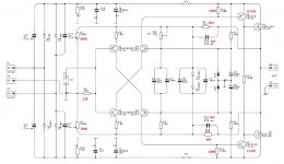
I am building Nico's Lateral-MOSFET version. I wanted more gain so I will change the ratio of R9/R1. I also a bit more current thru the drivers: 2SA1145Y & 2SC2705Y so I will decrease R11 & R12 to 240R. R13 will be a trimmer. I guess that I will need a pre-amp to drive the SSA but I will change R5 to the value recommended by MiiB.
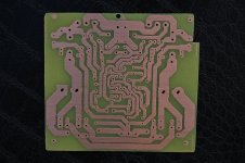
I have made the PCB (a redrawn based on AlexMM Rev 1.4) & I will build the SSA over the weekend.
Any comments about the proposed changes.
Cheers, Stanley
I am building Nico's Lateral-MOSFET version. I wanted more gain so I will change the ratio of R9/R1. I also a bit more current thru the drivers: 2SA1145Y & 2SC2705Y so I will decrease R11 & R12 to 240R. R13 will be a trimmer. I guess that I will need a pre-amp to drive the SSA but I will change R5 to the value recommended by MiiB.
I have made the PCB (a redrawn based on AlexMM Rev 1.4) & I will build the SSA over the weekend.
Any comments about the proposed changes.
Cheers, Stanley
Attachments
Hi all,
I am building Nico's Lateral-MOSFET version. I wanted more gain so I will change the ratio of R9/R1. I also a bit more current thru the drivers: 2SA1145Y & 2SC2705Y so I will decrease R11 & R12 to 240R. R13 will be a trimmer. I guess that I will need a pre-amp to drive the SSA but I will change R5 to the value recommended by MiiB.
I have made the PCB (a redrawn based on AlexMM Rev 1.4) & I will build the SSA over the weekend.
Any comments about the proposed changes.
Cheers, Stanley
On Alexmm 1.4 R13 seems to be a 2 or 3W resistor...A multiturn trimer is usely rated for 0.5W. Could it be an issue there if you completely replace R13 by a trimer?
Marc
Lazy Cat, in my experiments i used 0.1uF but i see no reason that 1uF should not work too. I found that un bypassed fuses are ( slightly ) audible, even when they are in the feedback loop. I am planning to build one of your designs here. I have high sensitivity speakers so even 50W is more then enough for me. I actually was struck by your first version with lateral Fets that drive the speakers from the drains. I think something like that heavy into class A is what i would like to build. 25W would be alright with me. The changes you made later lowered THD and raised power but i am not sure if such amps drive actual speakers dynamically better. I really think one should connect a speaker plus cable when one measures an amp. I know Peter Schüller very well. He leads an independent lab that measures for example amps for various high end audio magazines. Most amps today measure very good on a dummy load but have a totally different dynamic behavior and distortion over frequency and level when a speaker is connected. Also the order of the distortion is important. Some amplifiers show higher order distortion ( say more 3rd and 5th then 2nd ) when connected to a speaker and the amount of individual harmonics is not changing linear with level. It is a complicated matter but THD simulated does not tell me much about the actual sound of the amplifier.
What i like with your designs is the speed and the low noise. I worked with Hiraga and Hawksford by the way so what you do looks very familiar to me. I only have to make up my mind what topology i will build.
What i like with your designs is the speed and the low noise. I worked with Hiraga and Hawksford by the way so what you do looks very familiar to me. I only have to make up my mind what topology i will build.
On Alexmm 1.4 R13 seems to be a 2 or 3W resistor...A multiturn trimer is usely rated for 0.5W. Could it be an issue there if you completely replace R13 by a trimer?
Marc
Thanks Marc,
I will leave the R11, R12 & R13 as suggested by Nico. I will measure the voltage drop across R13 to see if I need a higher wattage resistor.
Cheers, Stanley
I found that bypassing the fuse holder with a film cap sounds better.
Even if you solder fuses to the holder? So, what makes it different from bypassing plain wire? Maybe off topic, but i have to ask this one.
I asume that the fuse has a temp co. Soldering the fuse is a bit unconvenient i think.
Anyway, this is not important. I do it that way. One important client of mine claimed that the amp sounded worse when i put fuses in. This little trick rescued the deal and the patient was happy. Maybe the placebo effect was at work. If you do not like it or hear no difference leave it out.
Anyway, this is not important. I do it that way. One important client of mine claimed that the amp sounded worse when i put fuses in. This little trick rescued the deal and the patient was happy. Maybe the placebo effect was at work. If you do not like it or hear no difference leave it out.
fuses.
Are we talking bypassing or decoupling?
Bypass seems like the cap is installed with one end on the input to the fuse holder and the other cap end to the output from the fuse holder.
Decoupling seems like the cap is connected one end to the outlet from the fuse holder and the other cap end is connected to Power Ground.

Hi to all 
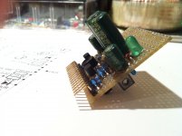
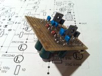
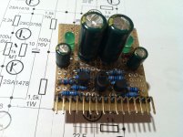
I had quite a busy week but still manage to put together SSA High Performance front-end-VAS which will be connected to my big metal BIGBT's soon. I intentionally made it on proto board, regardless Alex's PCB already present. The reason is in high-freq testing on the way, for that shortest possible tracks, star layout and some specific HF rules to follow are needed. So I came up with something like shown on pics and will be put on the test soon, hardly wait ...
I had quite a busy week but still manage to put together SSA High Performance front-end-VAS which will be connected to my big metal BIGBT's soon. I intentionally made it on proto board, regardless Alex's PCB already present. The reason is in high-freq testing on the way, for that shortest possible tracks, star layout and some specific HF rules to follow are needed. So I came up with something like shown on pics and will be put on the test soon, hardly wait ...
Attachments
Hi to all
I had quite a busy week but still manage to put together SSA High Performance front-end-VAS which will be connected to my big metal BIGBT's soon. I intentionally made it on proto board, regardless Alex's PCB already present. The reason is in high-freq testing on the way, for that shortest possible tracks, star layout and some specific HF rules to follow are needed. So I came up with something like shown on pics and will be put on the test soon, hardly wait ...
Hi Lasy Cat,
That's exactly what i had in mind in post #645....i will follow with great attention.
I have some difficulty to purchase exicon ones so i will try first the SSA-BIGBT for wich i have most parts by side. Need just to redrawn Alexmm for my smoothing caps and double bridge.
Marc
PS : is there any utility to let space for caps in //of feed back 1K resistors on SSA_BiGBT?
Last edited:
PS : is there any utility to let space for caps in //of feed back 1K resistors on SSA_BiGBT?
Feedback pF caps can always be added on the bottom side of PCB parallely to 1k feedback resistors, or you can put them on the top of the PCB, it's up to you.
I didn't have them in action or any other HF compensating caps at this SSA design, cause I have never noticed any hint of oscillation in any circumstances, not even in heavy clipping conditions (clean-flat cut at rail level). But anyway it's good to have them in to determine the exact end of power bandwidth of the amp
At this front-end-VAS test module from the upper post I will extensively test supply current injection to the input pair BJT's by CCS's or by resistors only. Better sounding solution will be used to further design development, with detail explanation in this thread of course.
Last edited:
- Status
- This old topic is closed. If you want to reopen this topic, contact a moderator using the "Report Post" button.
- Home
- Amplifiers
- Solid State
- Simple Symetrical Amplifier